Copyright
©The Author(s) 2015.
World J Gastroenterol. Jan 21, 2015; 21(3): 759-785
Published online Jan 21, 2015. doi: 10.3748/wjg.v21.i3.759
Published online Jan 21, 2015. doi: 10.3748/wjg.v21.i3.759
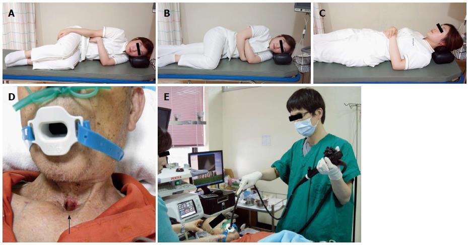
Figure 1 Examinee.
A, B: Example of left lateral decubitus position. To avoid an increased intra-abdominal pressure while lying in a left lateral decubitus position, it is recommended to bend the legs; C: Example of supine position; D, E: The examinee is undergoing an upper gastrointestinal endoscopy while lying in a supine posture due to hemiplegia and tracheotomy (arrow mark).
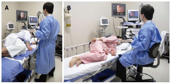
Figure 2 Standing and sitting method.
A: As the upper gastrointestinal endoscopy takes a relatively short time, most examiners conduct the procedure in the standing posture; B: If the standing method puts too much strain on the body of an examiner such as in case of pregnancy, she can use the sitting method to perform the procedure.
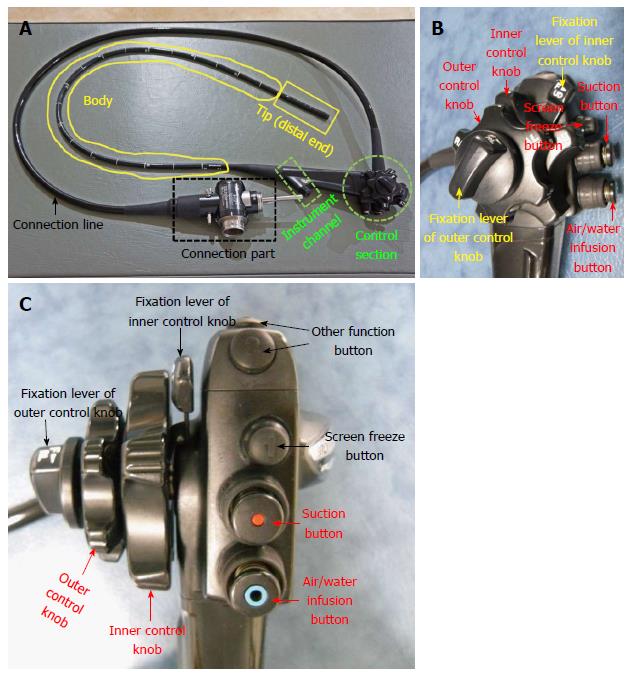
Figure 3 Components of the endoscope.
A: Typical upper gastrointestinal endoscope (Olympus GIF-H260). Although there might be slight differences in the structure of the endoscope between manufacturing companies, the overall structure will be nearly identical; B, C: Magnified view of control section; lateral and forward views.
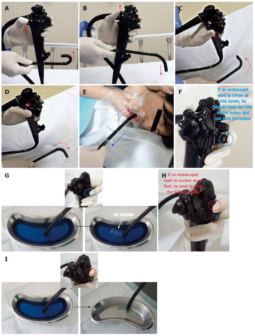
Figure 4 Basic technique.
A: Up deflection; B: Down deflection; C: Left deflection; D: Right deflection; E: Push forward (red arrow) and pull back (blue arrow); F: Air inflation. Simple closure of hole in the Air/Water infusion button activates it, one is not required to push the button. If an endoscopist wishes to infuse air into lumen, he or she should close the hole of this button, and should not push the button; G: An example of air inflation; H: Air suction. If an endoscopist wants to suction air or fluid, he needs to push the suction button; I: An example of water suction.
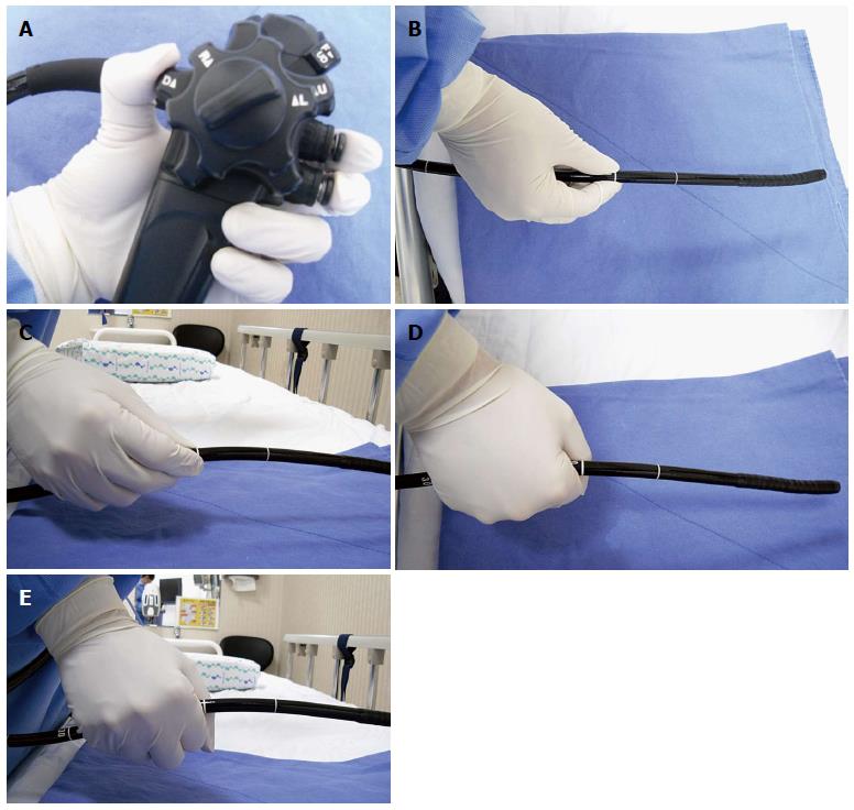
Figure 5 Endoscope gripping method.
A: Holding the control part of the endoscope with the left hand; B, C: Grabbing the distal end of the endoscope with the right hand. It is recommended than one gently hold the shaft approximately 15-20 cm away from the tip as if to shake hands; D, E: Wrong gripping methods. If the shaft is held with a firmly clenched fist, the endoscopist will have difficulty handling the scope. Therefore, the shaft should not be held too tightly.
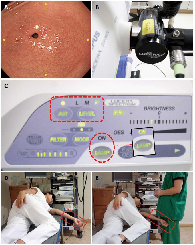
Figure 6 Pre-intubation preparation.
A: The endoscopic image displayed on the monitor. A beginner endoscopist must remember that the direction (arrow marks) on the screen coincides with that of the movement of the endoscope. Therefore, for example, if one wants to see a lesion on the upper side, one can angle the tip of the endoscope upward; if one wants to see a lesion on the lower side, one can angle it downward; if one wants to see a lesion on the left or right side, you can angle it to the left or right, respectively; B: Connection part where the endoscope is plugged into the mainframe. If there is any defect in the arrow-marked part, an endoscopist will encounter difficulty advancing the scope due to insufficient air insufflation; C: Mainframe. There are many buttons to control a variety of functions. Among them, the control button for air insufflation (dotted rectangle) is set to a low level for the colonoscopy, while the esophagogastroduodenoscopy is performed at a high level of air insufflation. Apart from them, there is the light source button (dotted circle). If the light source button turns off, an image on the screen becomes invisible, which makes it impossible to proceed with an endoscopy. Therefore, endoscopies must be always performed after checking whether the light source functions properly; D, E: Wrong position of arm. If an arm of an examinee is protruding out of the bed, it can touch the body of the endoscopist and interfere with the examination.
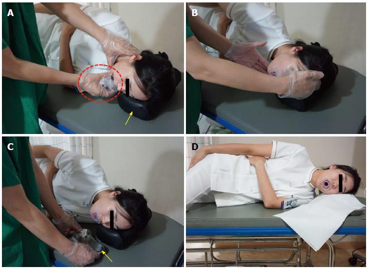
Figure 7 Intubation of scope from oral cavity into pharynx.
A: The examiner is inserting a mouthpiece into the mouth of the examinee (dotted circle). The pillow (arrow mark) helps keep the neck and head straight with the trunk; B: To ensure a smooth insertion of the endoscope, the examiner needs to raise the chin of the examinee and have the head protrude a little bit forward. If this happens, the tongue base separates from the hypopharynx so that the insertion of the endoscope is easier; C: A small container is placed close to the mouth of a patient to collect saliva during and after the esophagogastroduodenoscopy; D: The examinee with a mouthpiece placed in the mouth is fully ready for the examination.
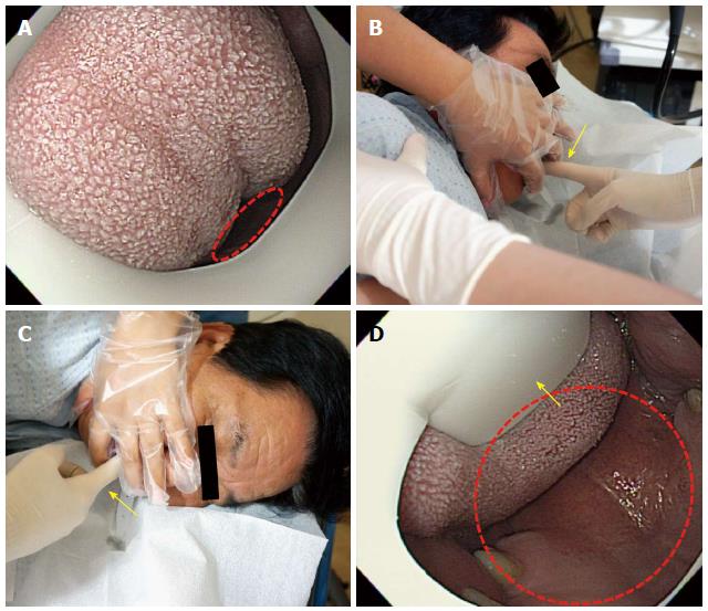
Figure 8 Intubation of scope from oral cavity into pharynx.
A: Tongue blocking the oral cavity. As the oral cavity has a very narrow space (dotted circle) in this case, it is difficult to insert the scope (B, C). The examiner pushes aside the examinee’s tongue with his or her index finger (arrow mark) to secure more space; D: Tongue placed under the tongue restrainer (arrow mark). After securing more space, the insertion of the scope is easier.
Figure 9 Intubation of scope from oral cavity into pharynx.
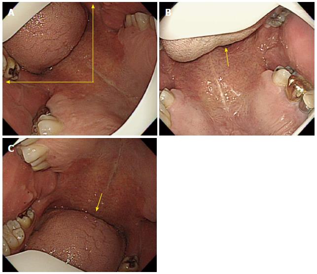
A: The right position of the tongue. Before inserting the endoscope into the oral cavity, it is recommended the the tongue be positioned between the 9 o’clock and 12 o’clock directions on the screen. An advanced endoscopist usually inserts the endoscope into the oral cavity after placing the tongue to the upper left side (11 o’clock direction) on the screen; B: Another example of a properly positioned tongue. In this case, the tongue is placed nearly to the 12 o’clock direction on the screen; C: Inadequately positioned tongue. As the tongue is placed in a wrong position (about 6 o’clock direction in this examinee’s case) on the screen, it becomes difficult to advance the scope further because the intended manipulation of the scope does not coincide with the subsequent movement of the scope displayed on the screen.
Figure 10 Intubation of scope from oral cavity into pharynx.
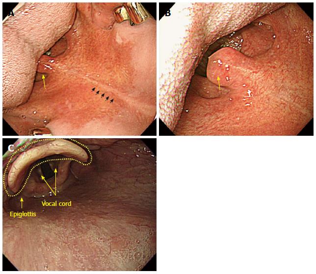
A: After placing the tongue in a right position on the screen, an examiner has to advance the scope along the middle line (small arrow marks) of the soft palate. The uvula is observed in the upper side of the tongue (lower side); B: The uvula is observed more clearly at the end of the tongue (tongue base). After that, rotate the scope a little bit to the left and advance it further; C: If the scope is advanced further, it will enter the hypopharynx where the epiglottis is observed together with the vocal cord.
Figure 11 Intubation of scope from oral cavity into pharynx.
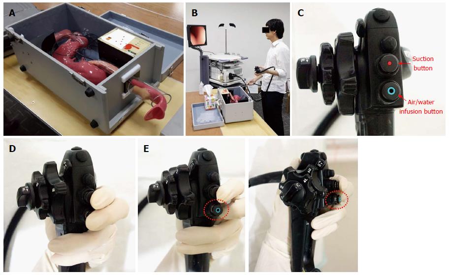
A: The human body model for esophagogastroduodenoscopy (EGD) training; B: Practicing the endoscopic procedure using a model of a human body. This human body model is specially designed for EGD training, and if beginners practice EGD using a human body model, it will be helpful for them to acquire and improve their capacity to perform the procedure; C: The control part of the endoscope has several buttons to manipulate various functions. Among them, there are two buttons that play a critical role in relation to the procedure; the “suction button” and the “air/water infusion button”; D: When one is advancing the scope, it is recommended to place the second and third fingers on the suction button and the air/water infusion button, respectively, after inserting the distal tip into the upper esophagus. The reason for placing the fingers on the buttons is to continuously insufflate air into the lumen during the upper GI endoscopy; of course, an excessive air infusion is absolutely taboo, and in that case, an endoscopist should stop air insufflation and begin to suction the air. Another reason is it makes it easier to immediately suction liquid or air whenever it is judged to be necessary by the examiner; E: The recommended position of the third finger until advancement into the upper esophagus (the cervical part of esophagus). As mentioned above, if a finger is placed on the air/water infusion button (that is to say, if the vent is blocked by a finger), this itself can irritate the airway (trachea) and trigger coughing and vomiting reflexes. As the air insufflation and water infusion use the same channel, a few droplets of water can be released when an examiner starts to do an air infusion, which can also cause coughing or vomiting reflexes. Therefore, it is recommended that an examiner not block the vent on the top of the air/water infusion button with the third finger of the left hand, until the distal tip reaches the entrance of the upper esophagus, as shown in the picture.
Figure 12 Intubation of scope from oral cavity into pharynx.
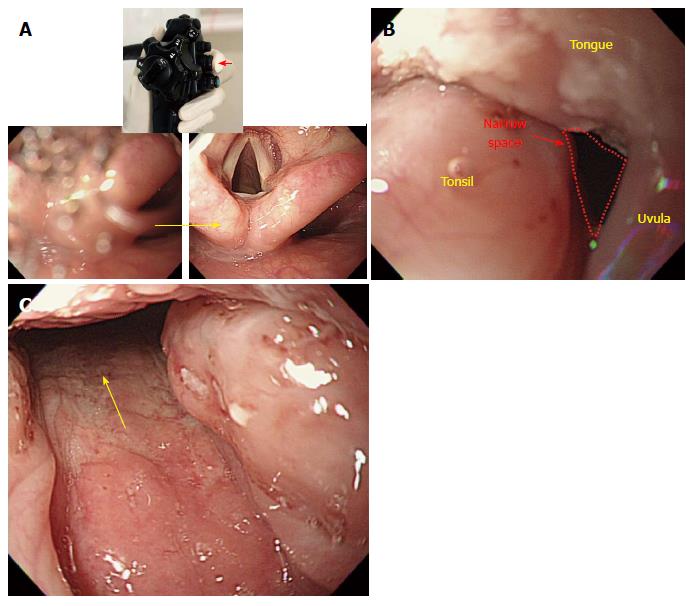
A: If the visibility is compromised by saliva in the process of advancement after inserting the scope into the oral cavity (left), one can secure clear visualization of the entrance route (right) by suctioning the saliva with a push on the suction button (small arrow mark). If one advances the scope into the esophagus without suctioning the saliva, an examinee may inhale saliva, which can cause a severe coughing reflex. Therefore, it is recommended to suction saliva during the advancement process; B: Swollen tonsil. As the pathway where the tongue, uvula and tonsil are located together is narrow due to a swollen tonsil, it can be difficult to advance the scope, and a beginner may feel frustrated. However, as the endoscope is ductile, the scope can pass into the oropharynx if it is twisted carefully (to the right, in this case); C: Passage through the swollen tonsil.
Figure 13 Intubation from hypopharynx to upper esophagus.
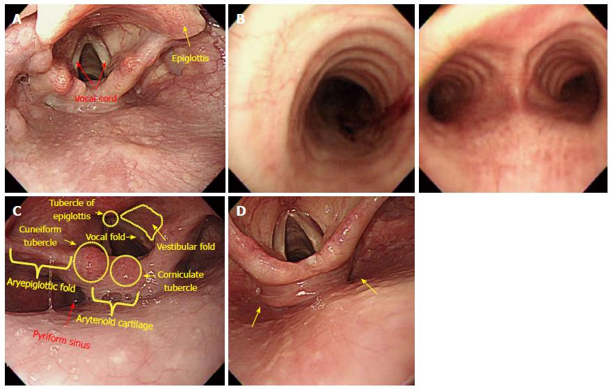
A: Hypopharynx. The hypopharynx refers to a part of the pharynx located in the posterior of the larynx (usually from the epiglottis to the vocal cord); B: Bronchus. If the scope is mistakenly inserted into the vocal cord, the circular cricoid cartilage, which belongs to the main bronchus (left), is observed. If the scope is passed further without noticing that it has been placed in a wrong position, the scope will enter the area (right) where it bifurcates into the left and right sides. When an examinee suffers a coughing reflex together with severe dyspnea, the scope must be immediately withdrawn; C: Anatomical structures of hypopharynx and larynx; D: Left- and right-sided pyriform fossa. As an examinee lies in a left lateral decubitus position, it is usually recommended to insert the scope into the left sided pyriform fossa. However, after several attempts to insert the scope have failed and ended with damaged tissues, advancement into the right-sided pyriform fossa should be attempted.
Figure 14 Intubation from hypopharynx to upper esophagus.
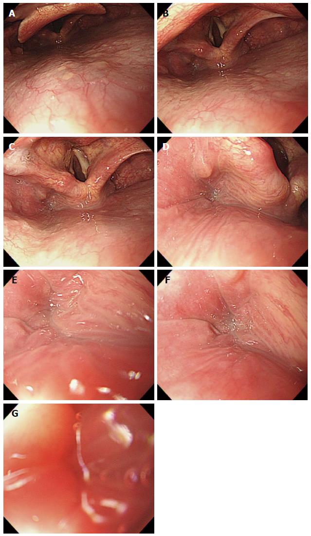
A-E: Images were continuously taken during the advancement of the scope through the left-sided pyriform fossa into the upper esophagus. Although it appears to have a blind ending shape, upon further examination, a tiny furrow will be observed. With air insufflation and by a little bit of force, the scope can be moved into the upper esophagus, despite resistance from its sphincter; F, G: In this process, a red-out sign can occur. Continue to insert the scope gradually and carefully while observing the surface in the process of the advancement into the lumen.
Figure 15 Insertion from esophagus to stomach.
A: Esophageal physiology, the second stenosis. If the scope is advanced 10 cm further after passing it through the sphincter of the upper esophagus, a high pressure zone caused by aortic arch (dotted line) on the left side, and another high pressure zone by the left main bronchus on the right side of the distal antrum can be seen. Depending on the examinees’s posture, or condition, state of air insufflation, there are some cases where such pressure marks are clearly visible; B: Pressure marks by the aortic arch and the left main bronchus, with a pressure zone caused by a vertebral body positioned in the 6 o’clock direction on the screen with a slightly rotation of the scope (knuckle line). The advancement direction inside the esophagus is usually described based on the condition that a high pressure zone by the vertebral body is positioned toward the 6 o’clock direction on the screen. However, if those pressure marks by the vertebral body are not clearly visible, the lumen of the esophagus is not wide enough. In that case, it is acceptable to describe their vertical locations (usually the insertion length from the incisor) unlike the description of directions inside the stomach; C: Pressure by a calcified aortic arc. A severe case of calcification can look like a submucosal tumor, due to the conspicuous appearance of pressure marks; D: Gastroesophageal junction (GEJ) before suctioning air. The boundaries of the GEJ (arrow mark) are not clearly visible; E: GEJ after suctioning air. As the GEJ unfolds, the boundaries of the GEJ become clear; F: The direction of the scope in the esophagus. The scope is inserted using a straight line progression (arrow mark) in the esophagus; G-I: An esophageal web around the GEJ. If the mucous membrane of the esophagus has a rather curved progression (arrow mark in I), it is recommended to insert the scope by slightly rotating the shaft rather than pushing it straight ahead forcefully; I: Esophageal diverticulum: it appears as though the progression of the esophagus has two different directions. If being pushed in a hurry, a scope can enter the esophageal diverticulum, which can cause a perforation; J: Esophageal diverticulum after pulling back the scope. After filming the entire entrance of the esophageal diverticulum by pulling back the scope, advance it into the lumen of the esophagus; K, L: Endoscopic image of a severe case of esophageal diverticulum. In the case of a patient with a severe esophageal varix, extra caution needs to be taken during the insertion and advancement of the scope into the esophagus. A massive hemorrhage here can lead to the death of an examinee.
Figure 16 Intubation from stomach to duodenal bulb.
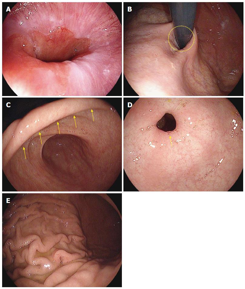
A: Gastroesophageal junction (GEJ). In absence of hiatal hernia, the GEJ lies next to the cardia; B: Gastric cardia observed in retroflexion of the scope. Likewise, in the absence of hiatal hernia, the gastric cardia is located next to the gastroesophageal junction; C: Gastric angle. If the distal tip of the scope is deflected upward in the distal antrum, the gastric angle (arrow marks) in an arched shape will be observed; D: Pyloric ring. The pyloric ring is usually observed to have a circular shape (arrow mark); E: Gastric fold. For a patient who does not have a severe case of atrophic gastritis, the gastric fold serves as a landmark to distinguish the body of stomach from the antrum of stomach.
Figure 17 Intubation from stomach to duodenal bulb.
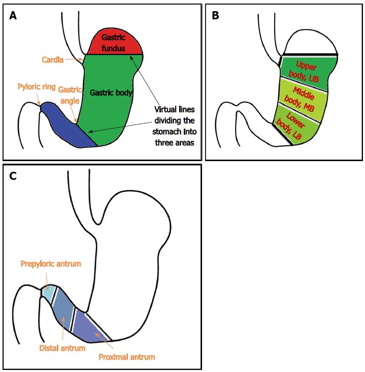
A: Schematic diagram of the anatomy of the stomach. Based on the landmarks, the stomach is divided into three parts: the gastric fundus, gastric body and gastric antrum; B: A schematic diagram of gastric body subdivided into three areas. The gastric body is the largest among the three parts. Therefore, the gastric body can be subdivided into three areas: upper body, middle body and lower body; C: Schematic diagram of three subdivided areas of the gastric antrum.
Figure 18 Intubation from stomach to duodenal bulb.
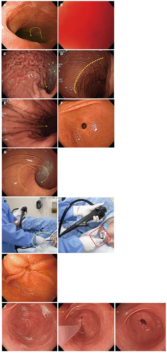
A: Gastroesophageal junction (GEJ). As the lower esophagus penetrates through the diaphragm and then starts to progress in the left posterior direction at a point where it is connected to the stomach, it is recommendable to insert the scope by twisting the shaft to the left side (arrow mark) during intubation into the stomach; B: Red-out sign. If the scope is only pushed in a straight line, it can subsequently touch the posterior wall of the gastric body, in which a red-out sign appears. If this happens, just pull back the scope a little. If air is insufflated, clear visibility will result; C: Gastric fold. When the scope is first inserted from the GEJ into the lumen of the stomach, a gastric fold is observed. Gastric fluid (small arrow marks) is usually retained in the gastric fold (greater curvature). The progression direction into the antrum of stomach is usually to the right side. The examinee in this image has a right sided progression of the surface into the antrum of stomach (5 o’clock direction, big arrow mark); D: Watershed. The watershed is also often called the saddle area, which serves as a landmark to divide the stomach into the gastric fold, fundus, and gastric body. It may not be clearly visible depending on the examinees or the condition of air insufflation; E: Advancement into the antrum of stomach; F: Distal antrum. The pyloric ring in a circle-shape is observed (arrow mark); G: Endoscopic image of cascade stomach. As the deflection angle of the cascade stomach is extremely sharp, a beginner may encounter difficulty advancing the scope into it; H: Tips for the insertion of the scope into the pyloric ring. When the endoscopy is performed in the stomach, it is a common practice to hold a shaft by keeping some distance from the mouth of the examinee (approximately 10 cm). However, especially when inserting the distal tip into the pyloric ring, it is advisable to hold it short (dotted rectangle) because it can transfer force to the tip more efficiently, to help advance it into the pyloric ring; I: Closed pyloric ring, a challenging configuration for beginners; J: Injection of warm water into the pyloric ring. The injection of warm water is helpful in inserting the scope into the pyloric ring.
Figure 19 Insertion from duodenal bulb into the descending portion of duodenum.
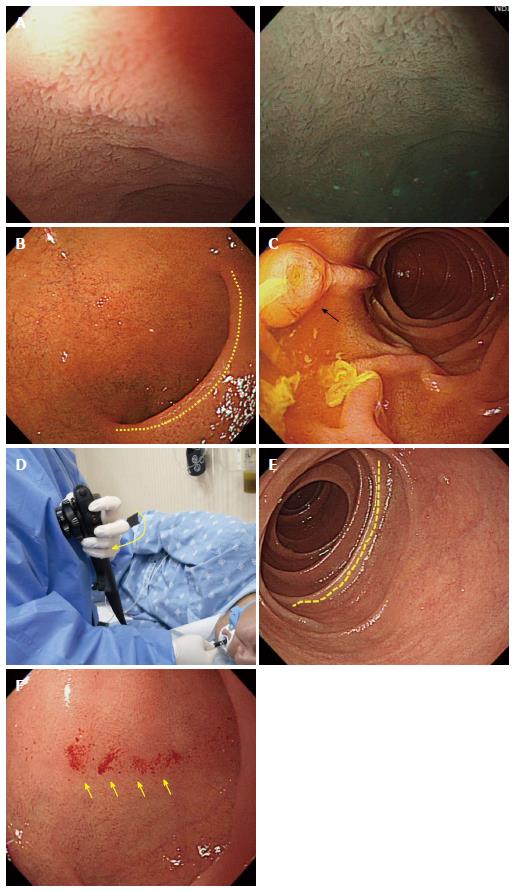
A: Villi in the duodenal bulb. Water-filling method (left) and narrow-banding image (right); B: Typical image of a normal duodenal bulb. The superior duodenal angle in a crescent shape is observed on the right side. This direction coincides with the progression direction into the second portion of duodenum (descending part); C: Descending part of duodenum. The AOV is observed; D: Image of the left hand when inserting the scope into the descending part of duodenum from the duodenal bulb. It is advisable to pull the left hand holding the control part close to the chest (arrow mark), as it will help insert the scope into the descending part of duodenum. If one fails to advance the scope into the descending part of duodenum by rotating the shaft to the right in the SDA, it is recommendable to try to angle the scope more sharply to the right side or to do it in combination with an upward deflection of the distal tip of the endoscope; E: Circular fold (Kerckring) observed in the descending part of duodenum; F: Bleeding marks on the mucous membrane due to a collision with the endoscope during the advancement from the ampulla into the descending part of duodenum. A smooth insertion of the scope is needed in order to avoid leaving bleeding marks during the advancement into the entrance to the descending part of duodenum. However, if the body of an examinee moves during the endoscopy, even a skilled endoscopist can leave bleeding marks while trying to insert the scope into the descending part of duodenum. Therefore, it is recommended to film the images of the duodenal bulb before inserting the scope into the descending part from the duodenal bulb.
Figure 20 Withdrawal of scope and observation, J-turn and U-turn.
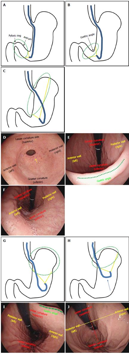
A: Schematic diagram of the J-turn. Deflect the distal tip of the scope upward in the antrum of the stomach; B: The shaft of the scope is bent in a J-shape, as the gastric angle in an arched shape is observed; C: If the scope tip is deflected upward more sharply, the lesser curvature of the gastric body can be observed; D: Endoscopic image of the antrum of stomach before maneuvering a J-turn. The pyloric ring (arrow mark) is observed in the front; E: Endoscopic image of the antrum of stomach after maneuvering a J-turn. If the distal tip of the endoscope is deflected upward, the gastric angle (dotted line) in an arched shape is observed. At this point, the upper side is the greater curvature; the lower side is the lesser curvature; the left side is the anterior wall; the right side is the posterior wall. The left and right directions on an endoscopic image taken during a J-turn maneuver are not reversed; F: Endoscopic image taken in the J-turn. In this case, the distal tip of the endoscope is deflected upward too sharply and the gastric angle cannot be observed. Likewise, the left and right directions on an image taken in J-turn do not change, but only the up and down directions are reversed in this case; G: Schematic diagram of the U-turn. The U-turn can be maneuvered by rotating the scope in a J-turn by 180 degree; H: In the U-turn, the observation is usually done while pulling the scope up toward the gastric cardia; I: Endoscopic image taken in the U-turn. A U-turn changes the directions of the left and right sides; the upper side is the lesser curvature; the lower side is the greater curvature; the left side is the posterior wall; the right side is the anterior wall; J: Endoscopic image after pulling up the scope in a U-turn toward the gastric cardia. The directions of the left and right sides still remain reversed.
- Citation: Lee SH, Park YK, Cho SM, Kang JK, Lee DJ. Technical skills and training of upper gastrointestinal endoscopy for new beginners. World J Gastroenterol 2015; 21(3): 759-785
- URL: https://www.wjgnet.com/1007-9327/full/v21/i3/759.htm
- DOI: https://dx.doi.org/10.3748/wjg.v21.i3.759


