Copyright
©The Author(s) 2015.
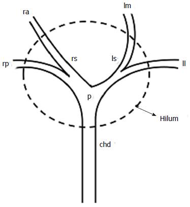
Figure 1 Schematic diagram showing structures forming hilum.
chd: Common hepatic duct; ll: Left lateral segmental duct; lm: Left medial segmental duct; ls: Left secondary confluence; p: Primary biliary confluence; ra: Right anterior segmental duct; rp: Right posterior segmental duct; rs: Right secondary confluence.
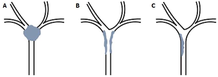
Figure 2 Schematic diagram showing three morphological types of hilar cholangiocarcinoma.
A: Nodular variety; B: Periductal infiltrating; C: Intraductal papillary.
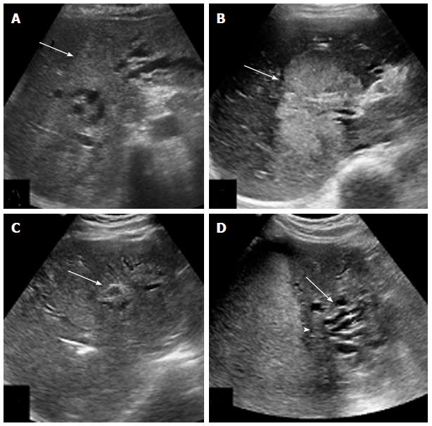
Figure 3 Ultrasonographic appearances of hilar cholangiocarcinoma.
A: Isoechoic lesion (arrow) involving primary biliary confluence; B: Hyperechoic mass (arrow) involving hilum; C: Infiltrative lesion (arrow) with periductal wall thickening; D: Atrophy of left lobe with crowding of bile ducts (arrow) due to isoechoic hilar mass (arrow head).
Figure 4 Post processing of computed tomography scan.
A: Coronal reformat showing ill-defined enhancing mass (arrow) in relation to hilum and common hepatic duct; B: Coronal thick maximum intensity projection showing same mass as in A (short arrow) with irregularity of right posterior hepatic artery (long arrow); C: Minimum intensity projection showing the extent of biliary involvement by the mass (arrow).
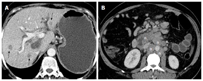
Figure 5 Axial contrast enhanced venous phase images.
A: Showing hilar mass (white arrow) with multiple liver metastases (black arrows); B: Showing multiple metastatic retroperitoneal nodes (n).
Figure 6 Axial contrast enhanced computed tomography scan in arterial (A), venous (B) and delayed (C) phases showing mild enhancement of the lesion (arrow) in arterial phase with persistence of enhancement in venous and delayed phases suggesting scirrhous nature of the lesion.
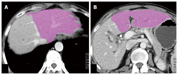
Figure 7 Axial venous phase computed tomography images (A and B) showing automated volumetry map with colour coding indicating the volume of future liver remnant (arrow).
Figure 8 Axial contrast enhanced computed tomography scan in arterial (A), venous (B) and delayed (C) phases of nodular variety of hilar cholangiocarcinoma (arrow) showing mildly enhancing ill-defined mass lesion in arterial phase with increasing enhancement in venous and delayed phases.
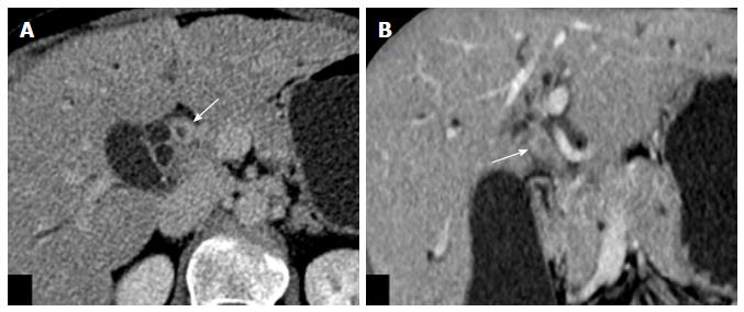
Figure 9 Axial (A) and coronal (B) images of venous phase of computed tomography scan of periductal infiltrating type of hilar cholangiocarcinoma showing wall thickening and enhancement of proximal common hepatic duct (arrow) causing luminal obstruction.
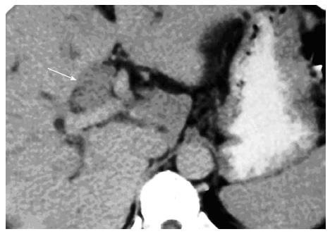
Figure 10 Axial contrast enhanced computed tomography scan in venous phase of papillary type of hilar cholangiocarcinoma showing minimally enhancing intraductal polypoidal lesion (arrow) causing distension of the duct.
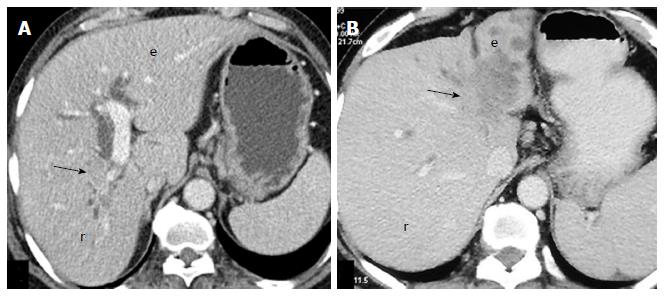
Figure 11 Axial computed tomography images showing atrophy of right lobe (r) due to hilar mass (arrow) in A, and atrophy of left lobe (l) caused by a mass (arrow) in B.
Figure 12 Axial computed tomography scan images showing vascular invasion.
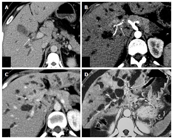
A: Small hilar mass (white arrow) abutting right hepatic artery posteriorly; B: Hilar mass (white arrow) encasing right hepatic artery causing irregularity in outline; C: Ill-defined hilar mass (white arrow) encasing portal vein and causing its narrowing (black arrow); D: Multiple collaterals (white arrows) seen in periportal and perigastric location due to portal vein obstruction.
Figure 13 Magnetic resonance cholangio-pancreatography images showing various appearances of hilar cholangiocarcinoma.
A: Smooth luminal narrowing (arrow); B: Complete hilar obstruction (arrow); C: Irregular asymmetric complete obstruction (arrow); D: Intraluminal filling defect (arrow).
Figure 14 Case of nodular type of hilar cholangiocarcinoma.
A: Axial T2-weighted magnetic resonance image show hypointensehilar mass (arrow) with biliary dilatation; B and C: Axial T1-weighted magnetic resonance images in arterial (B) and venous (C) phases showing mildly enhancing ill-defined mass lesion (arrow) encasing right hepatic artery and left portal vein.
Figure 15 Axial contrast enhanced T1-weighted magnetic resonance images in arterial (A), venous (B) and delayed (C) phases of periductal infiltrating variety of hilar cholangiocarcinoma showing mildly enhancing thick walled proximal hepatic duct in arterial phase (arrow) with increasing contrast enhancement in venous and delayed phases.
Figure 16 A case of periductal type of hilar cholangiocarcinoma.
A: Axial T1-weighted contrast enhanced magnetic resonance (MR) image in delayed phase showing enhancing periductal lesion (arrow); B and C: Axial diffusion weighted b-800 MR images (B) and ADC map (C) showing diffusion restriction of the lesion.
Figure 17 Axial (A) and coronal (B) computed tomography scan of a case of hilar cholangiocarcinoma after endoscopic stenting showing circumferential wall thickening of common hepatic duct around the stent.
It would be difficult to differentiate this from reactive thickening.
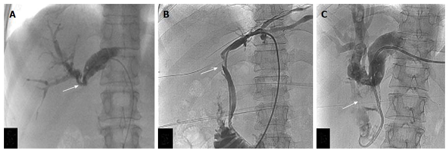
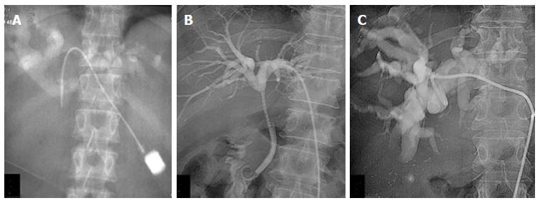
Figure 18 Percutaneous cholangiograms showing complete obstruction of common hepatic duct with patent primary biliary confluence (arrow, A), blocked primary biliary confluence with irregular outline (arrow, B) and intraluminal polypoidal filling defect (arrow, C).
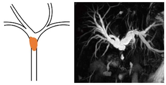
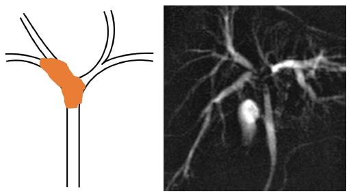
Figure 19 Schematic diagram and magnetic resonance cholangio-pancreatography image of type 1 hilar cholangiocarcinoma.
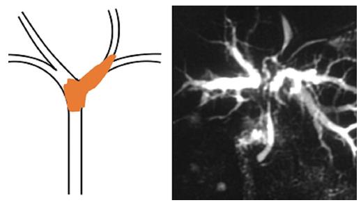
Figure 20 Schematic diagram and magnetic resonance cholangio-pancreatography image of type 2 hilar cholangiocarcinoma.
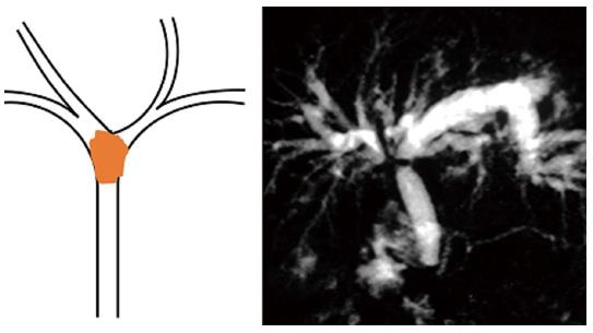
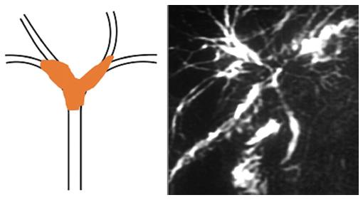
Figure 21 Schematic diagram and magnetic resonance cholangio-pancreatography image of type 3A hilar cholangiocarcinoma.
Figure 22 Schematic diagram and magnetic resonance cholangio-pancreatography image of type 3B hilar cholangiocarcinoma.
Figure 23 Schematic diagram and hilar cholangiocarcinoma image of type 4 hilar cholangiocarcinoma.
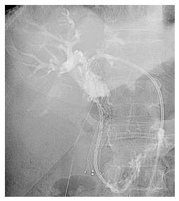
Figure 24 Types of biliary drainages.
A: Initial cholangiogram showing dilated intrahepatic bile ducts with hilar obstruction; B: Cholangiogram after placement of ring biliary catheter (Internal-External drainage) showing opacification of bile ducts and duodenum; C: Cholangiogram after placement of external drainage pig-tail catheter.
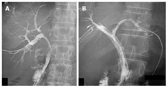
Figure 25 Types of biliary stenting.
A: Cholangiogram after placement of unilobar (right sided) biliary metallic stent; B: Cholangiogram after bilobar stent placement showing free flow of contrast into duodenum across the stricture.
Figure 26 Percutaneous biliary drainage through ring biliary catheter after obstruction of biliary metallic stent due to tumor ingrowth.
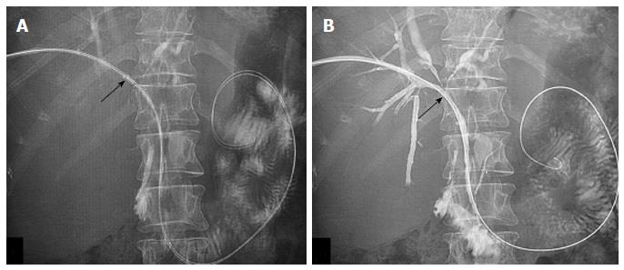
Figure 27 Percutaneous radiofrequency ablation for hilar cholangiocarcinoma.
A: Pre-radiofrequency ablation (RFA) image with probe in situ (arrow); B: Cholangiogram after RFA showing opening of obstruction (arrow).
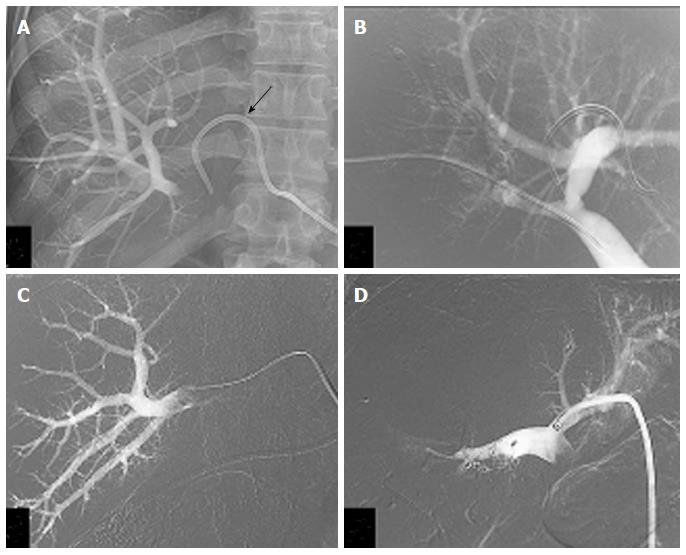
Figure 28 Right portal vein embolization with ipsilateral (A and B) and contralateral (C and D) approaches.
A: Right portal venogram with ipsilateral approach. percutaneous transhepatic biliary drainage catheter is seen (arrow); B: Portal venogram after embolization of right portal vein with PVA and glue; C: Right portal venogram with contralateral approach; D: Portal venogram after embolization of right portal vein with glue and vascular plug.
- Citation: Madhusudhan KS, Gamanagatti S, Gupta AK. Imaging and interventions in hilar cholangiocarcinoma: A review. World J Radiol 2015; 7(2): 28-44
- URL: https://www.wjgnet.com/1949-8470/full/v7/i2/28.htm
- DOI: https://dx.doi.org/10.4329/wjr.v7.i2.28


