Copyright
©The Author(s) 2024.
World J Clin Cases. Apr 6, 2024; 12(10): 1804-1809
Published online Apr 6, 2024. doi: 10.12998/wjcc.v12.i10.1804
Published online Apr 6, 2024. doi: 10.12998/wjcc.v12.i10.1804
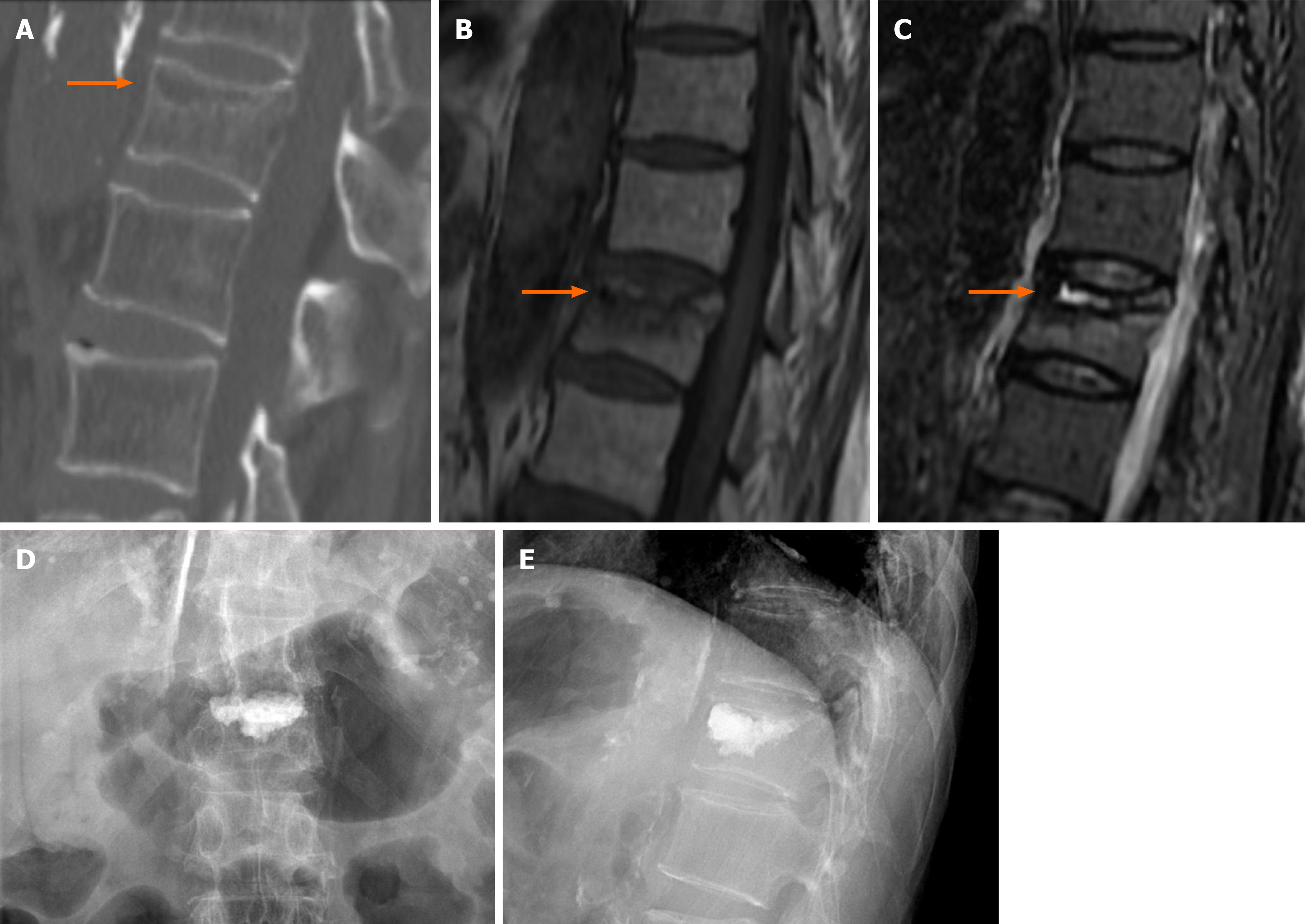
Figure 1 Pre- and post-operative images of T12 vertebral compression fracture.
A: preoperative sagittal computed tomography; B: preoperative T1-weighted magnetic resonance imaging (MRI); C: preoperative T2-weighted fat-suppressed MRI; D: postoperative anteroposterior radiograph; E: postoperative lateral radiograph. Orange arrow: The intravertebral cleft in the vertebra.
Figure 2 Cemented vertebral refracture and adjacent vertebral refracture after percutaneous vertebral augmentation.
A: preoperative sagittal computed tomography (CT); B: preoperative axial CT; C: bone scan; D: postoperative anteroposterior radiograph; E: postoperative lateral radiograph. Orange arrow: the intravertebral cleft in the vertebra; White arrow: the rupture of the posterior vertebral wall; Thin arrow: The fracture of T12 and L1 vertebrae; Bold arrow: Cement leakage in T12 vertebra.
- Citation: Zhang TD, Cao S, Ren HY, Li YM, Yuan YM. Cemented vertebra and adjacent vertebra refractured in a chronic kidney disease-mineral and bone disorder patient: A case report. World J Clin Cases 2024; 12(10): 1804-1809
- URL: https://www.wjgnet.com/2307-8960/full/v12/i10/1804.htm
- DOI: https://dx.doi.org/10.12998/wjcc.v12.i10.1804


