Copyright
©The Author(s) 2022.
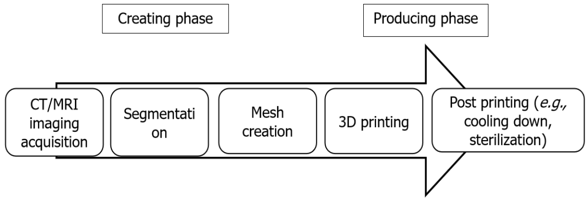
Figure 1 The process of three-dimensional printing.
A high-resolution computed tomography (CT) or magnetic resonance imaging (MRI) scan is required for the data acquisition of the limb deformity. The data are used for the segmentation process where each anatomical structure is processed as an individual entity. Mesh creation uses this data to generate the process from the segmented anatomy models into a model that only retains the specific structures that must be used for three-dimensional (3D) printing. Then, the 3D-printed model is manufactured. The post-printing process includes cooling down the created model or sterilization for the use in the operating room. CT: Computed tomography; MRI: Magnetic resonance imaging; 3D: Three-dimensional.
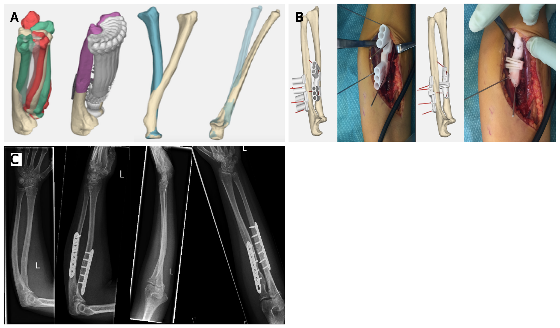
Figure 2 Three-dimensional-printed guides in posttraumatic rotational impairment of the forearm.
This patient suffered from a decreased rotational range of motion due to malunion after a forearm fracture. The three-dimensional (3D) deformity in both bones of the forearm was assessed with 3D analysis. During this analysis the optimal planes of correction were determined, and potential gains were calculated with simulation of rotation of the forearm comparing the preoperative and postoperative situation. Patient-specific guides to perform the desired osteotomies with predrilling of the screw holes for the radius and ulna are shown here. The surgical procedure was completed as planned and resulted in a vast improvement in range of motion. A: Preoperative planning; B: Intraoperative use of 3D-printed patient specific guides; C: Preoperative and postoperative radiographs, showing correction of the flexion deformity of the ulna to an ulna with a normalized proximal ulna dorsal angulation, as well as correction of an S-shaped radial shaft to a normalized bowing configuration of the radial shaft.
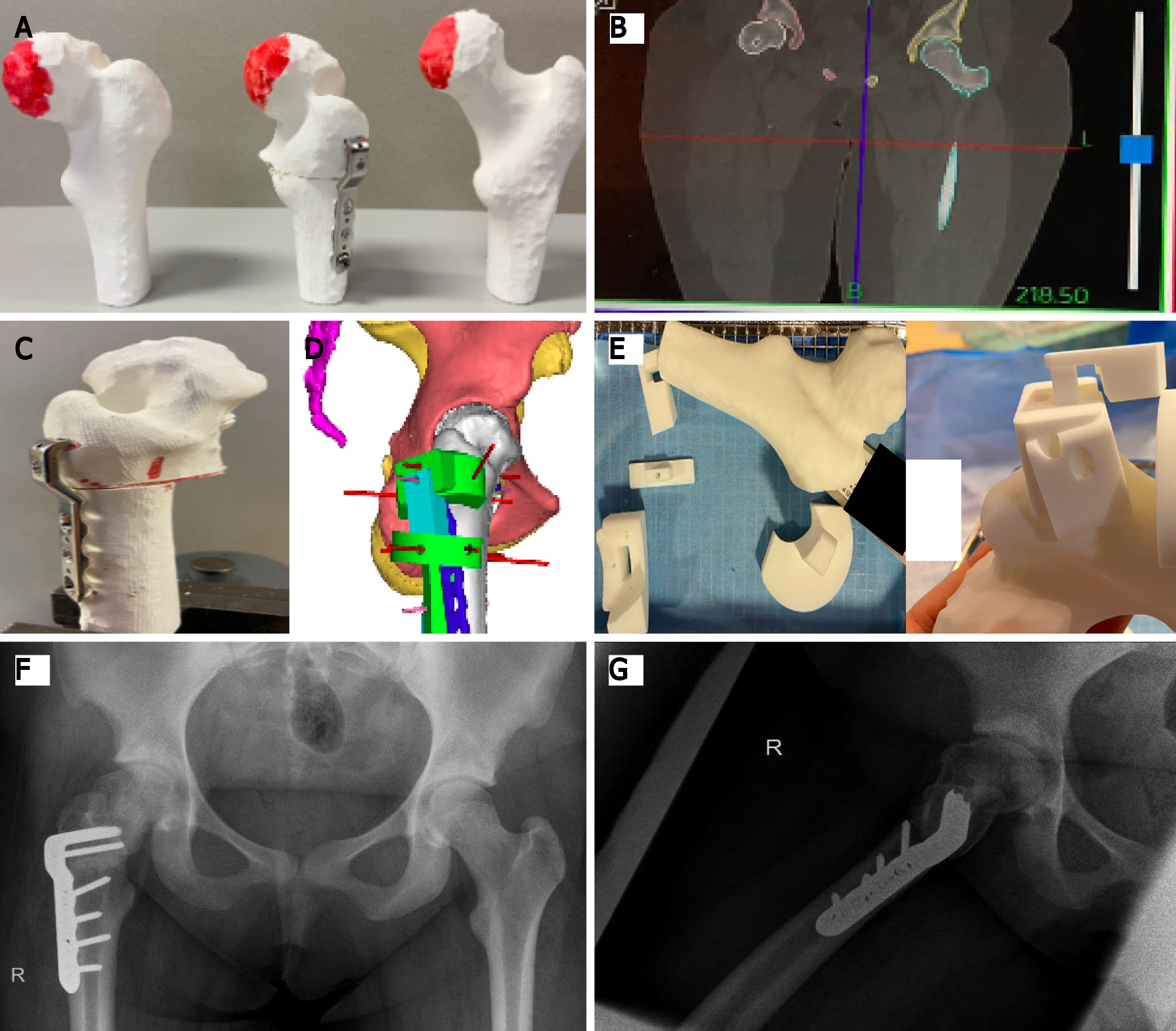
Figure 3 Three-dimensional printing for grade 3 slipped capital femoral epiphysis.
This figure shows different steps required in a case of grade 3 slipped capital femoral epiphysis where three-dimensional (3D)-based templates for positioning of the implant were used, and guidance of the osteotomy during the surgical procedure was performed. A: Preoperative 3D-printed model of the deformed femoral head; B: High-resolution computed tomography scan for exact preoperative planning of deformity correction; C: Preoperative 3D-printed model of the deformed femoral head after correction; D: Analysis of the unique blade plate through 3D-computed view; E: The 3D-printed unique locking system; F: Postoperative anteroposterior radiograph; G: Postoperative lateral radiograph.
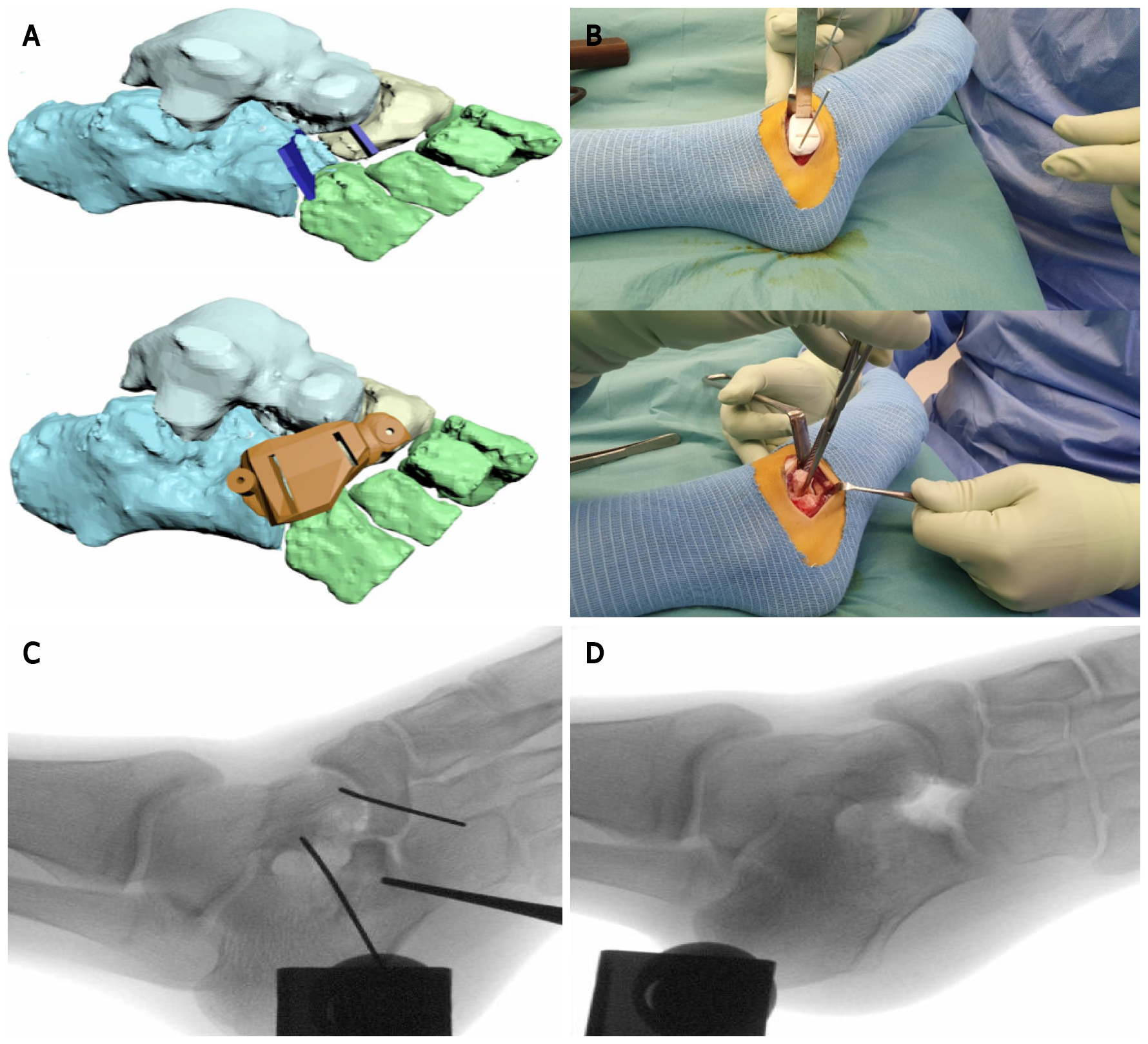
Figure 4 Preoperative planning and intraoperative use of three-dimensional-printing for a calcaneonaviculair coalition in a 14-year-old girl.
A preoperative magnetic resonane imaging scan was used to manufacture a three-dimensional (3D)-printed osteotomy guide for removal of a calcaneonavicular coalition. A: Preoperative 3D-planning; B: Intraoperative use of the manufactured 3D-printed guide and coalition resection; C: Intraoperative fluoroscopy shows the position of K-wires to hold the 3D-printed guide; D: Intraoperative fluoroscopy shows the resected bone.
- Citation: Goetstouwers S, Kempink D, The B, Eygendaal D, van Oirschot B, van Bergen CJ. Three-dimensional printing in paediatric orthopaedic surgery. World J Orthop 2022; 13(1): 1-10
- URL: https://www.wjgnet.com/2218-5836/full/v13/i1/1.htm
- DOI: https://dx.doi.org/10.5312/wjo.v13.i1.1


