Copyright
©The Author(s) 2015.
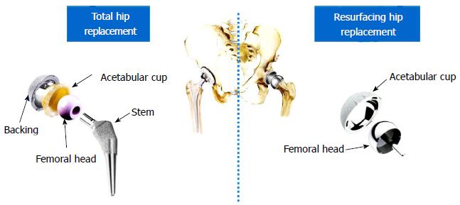
Figure 1 Total and resurfacing hip replacements.
Figure 2 Material couplings in hip implants.
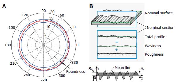
Figure 3 Nominal vs real surfaces.
A: Roundness; B: Roughness and waviness. Adapted from ASME B46.1-1995.
Math 24 Math(A1).
Math 25 Math(A1).
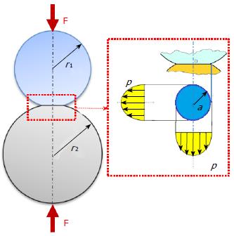
Figure 4 Hertz problem of spheres in contact.
Math 26 Math(A1).
Math 27 Math(A1).
Math 28 Math(A1).
Math 29 Math(A1).
Figure 5 Examples of finite element models of hip implants.
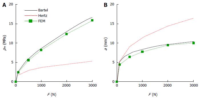
Figure 6 Maximum pressure (A) and contact radius (B) vs load for a MoP implant (head radius 14 mm, diametrical clearance 0.
2 mm, cup thickness 6 mm).
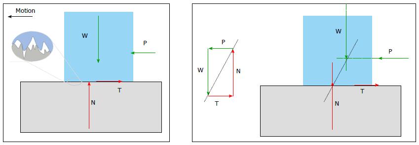
Figure 7 Microscopic detail of a rough contact.
Figure 8 Forces and equilibrium in sliding contact.
N and T are the normal and frictional forces acting on the upper body at the interface. Note that T is opposite to the motion direction. W and P are external forces. At the equilibrium force magnitudes must satisfy W = N and T = P; moreover the line of action of N + T must be the same of W + P.
Math 30 Math(A1).
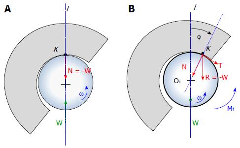
Figure 9 Forces in a revolute/spherical joint: Frictionless (A) and frictional contact (B).
Math 31 Math(A1).
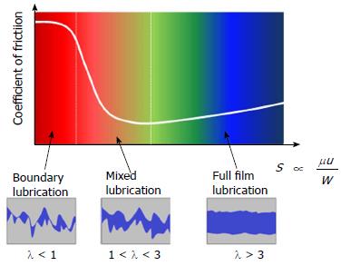
Figure 10 Stribeck diagram: Coefficient of friction vs Sommerfeld number and identification of lubrication regimes.
Math 32 Math(A1).
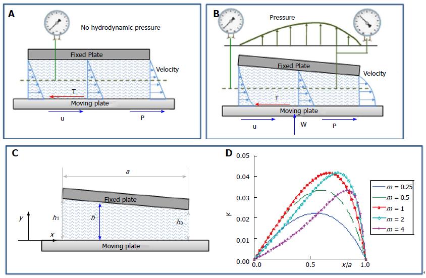
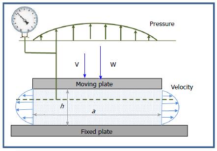
Figure 11 Hydrodynamic lubrication.
A: Parallel plates; B, C: Fixed inclined slider bearing; D: k plot from equation (12).
Math 33 Math(A1).
Math 34 Math(A1).
Math 35 Math(A1).
Math 36 Math(A1).
Math 37 Math(A1).
Math 38 Math(A1).
Math 39 Math(A1).
Math 40 Math(A1).
Figure 12 Squeeze film lubrication.
Math 41 Math(A1).
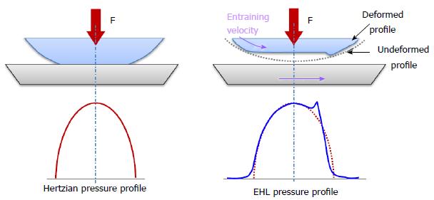
Figure 13 Dry and lubricated contact: From Hertzian to elastohydrodynamic lubrication pressure profiles.
EHL: Elastohydrodynamic lubrication.
Math 42 Math(A1).
Math 43 Math(A1).
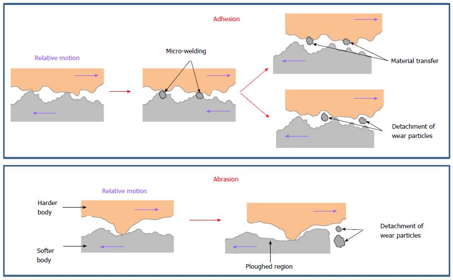
Figure 14 Adhesion and abrasion wear mechanisms.
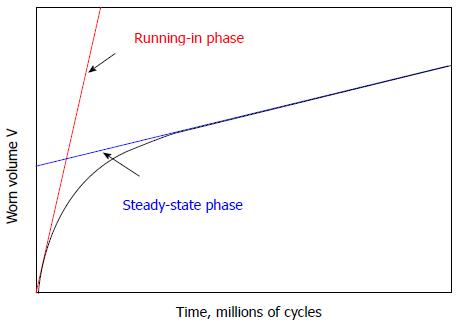
Figure 15 Wear trends vs time for metallic surfaces.
Figure 16 Anisotropic wear in UHMWPE: Cross shear phenomenon.
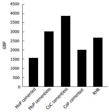
Figure 17 Averages implant prices.
MoP: Metal on plastic; CoC: Ceramic on ceramic; CoP: Ceramic on plastic; RHR: Resurfacing hip replacement.
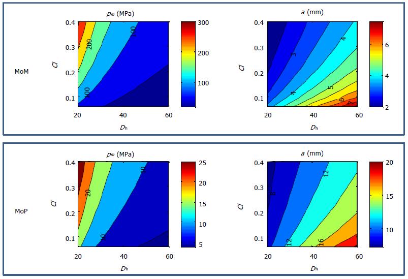
Figure 18 Maximum pressure pm and contact half-width a, for different Dh (mm) and Cl (μm), in metal-on-metal (E = 230 GPa, ν = 0.
3) and metal on plastic (E = 1 GPa, ν = 0.4) implants under 2500 N load. MoP: Metal on plastic; MoM: Metal-on-metal.
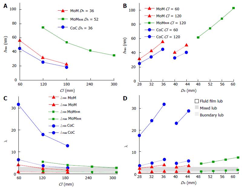
Figure 19 Effect of the clearance Cl and the head diameter Dh of hip implants on the lubrication, in terms of minimum film thickness (A, B) and dimensionless film thickness λ (C, D)[46].
Test case: W = 2 kN, ω = 2 rad/s, μ = 2.5 mPas. MoM: Metal-on-metal; CoC: Ceramic on ceramic; MoMRHR: Metal on metal resurfacing.
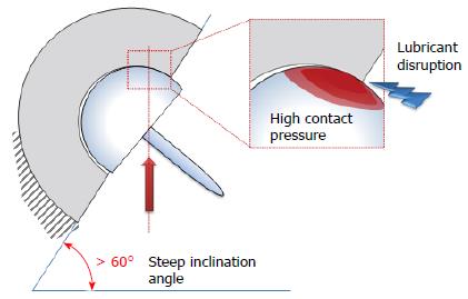
Figure 20 Edge loading phenomenon caused by steep cup inclination angles[52].
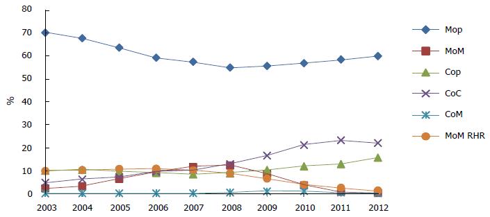
Figure 21 Trends in hip replacement implantation from 2003 to 2012.
Data from[3]. MoM: Metal-on-metal; CoC: Ceramic on ceramic; MoMRHR: Metal on metal resurfacing.
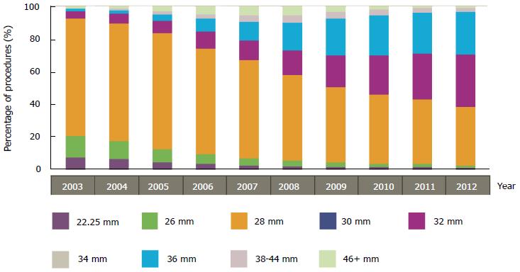
Figure 22 Trend of femoral head size from 2003 to 2012.
Data from[3].
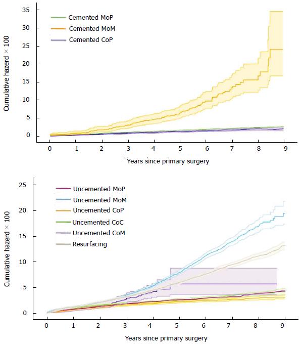
Figure 23 Revision risk (Cumulative hazard with 95%CI) for hip articulation.
Data from[3]. MoM: Metal-on-metal; CoC: Ceramic on ceramic.
- Citation: Puccio FD, Mattei L. Biotribology of artificial hip joints. World J Orthop 2015; 6(1): 77-94
- URL: https://www.wjgnet.com/2218-5836/full/v6/i1/77.htm
- DOI: https://dx.doi.org/10.5312/wjo.v6.i1.77


