Copyright
©The Author(s) 2017.
World J Orthop. Dec 18, 2017; 8(12): 929-934
Published online Dec 18, 2017. doi: 10.5312/wjo.v8.i12.929
Published online Dec 18, 2017. doi: 10.5312/wjo.v8.i12.929
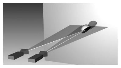
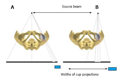
Figure 1 The scheme of model of anteroposterior pelvis view (X-ray source on the left) and anteroposterior hip view (X-ray source on the right) for acetabular cup of left hip.
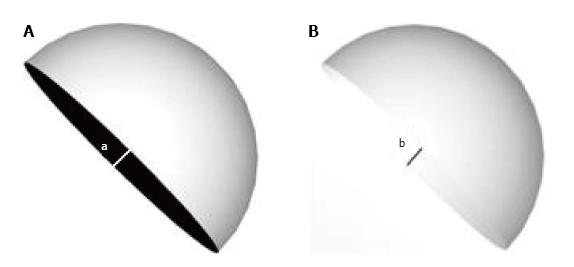
Figure 2 Different width of cup projections in pelvic and hip anteroposterior views.
A: Pelvic anteroposterior views; B: Hip anteroposterior views.
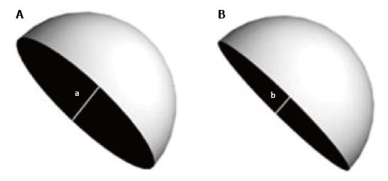
Figure 3 Acetabular component with anteversion angle of 20 degrees.
A: Acetabular component image for hip AP view; B: Acetabular component image for pelvic AP view, a > b. AP: Anteroposterior.
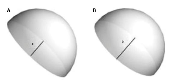
Figure 4 Acetabular component with retroversion angle of 20 degrees.
A: Acetabular component image for AP hip view; B: Acetabular component image for AP pelvic view, a < b. AP: Anteroposterior.
Figure 5 Acetabular component views with anteversion angle equal to half angle between rays of the beam.
A: Acetabular component image for hip AP view; B: Acetabular component image for pelvic AP view. Equal width of ellipse in both views, a = b. AP: Anteroposterior.
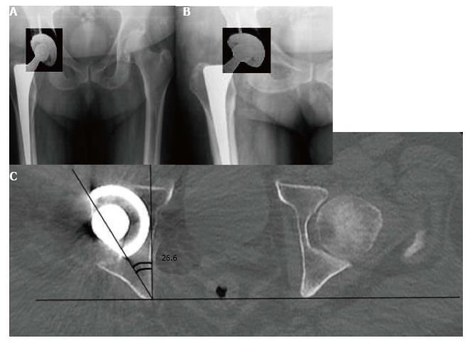
Figure 6 Retroversion sign in a patient with recurrent hip dislocations (enhanced contrasting applied to provide better recognition of acetabular cup ellipse).
A: AP Pelvic view; B: AP hip views; C: CT-scan of the same patient confirming acetabular component retroversion. AP: Anteroposterior.
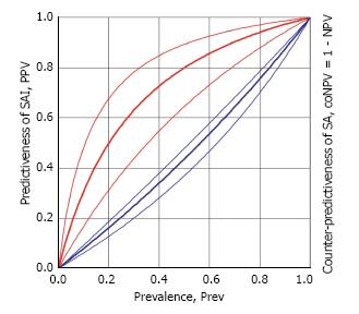
Figure 7 Predictiveness of sign of anteversion insufficiency appearance and counter-predictiveness of sign of anteversion appearance.
SAI: Sign of anteversion insufficiency; SA: Sign of anteversion.
- Citation: Denisov A, Bilyk S, Kovalenko A. Acetabular cup version modelling and its clinical applying on plain radiograms. World J Orthop 2017; 8(12): 929-934
- URL: https://www.wjgnet.com/2218-5836/full/v8/i12/929.htm
- DOI: https://dx.doi.org/10.5312/wjo.v8.i12.929


