Copyright
©The Author(s) 2016.
World J Orthop. Nov 18, 2016; 7(11): 738-745
Published online Nov 18, 2016. doi: 10.5312/wjo.v7.i11.738
Published online Nov 18, 2016. doi: 10.5312/wjo.v7.i11.738
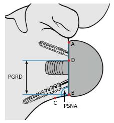
Figure 3 The prosthesis-scapular neck angle (PSNA) is the angle subtended by the intersection of line AB and line BC.
Point C is located 1 cm medial to the junction of the glenosphere and the most inferior and lateral bone of the inferior glenoid rim or scapular neck. The peg-glenoid rim distance (PGRD) is the distance between points B and D. PGRD: Peg-glenoid rim distance; PSNA: Prosthesis-scapular neck angle. Reprinted with permission from Simovitch et al[16], Figure 4A.
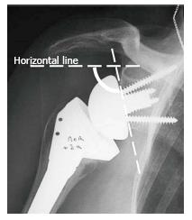
Figure 4 Glenoid inclination is the angle formed between a horizontal line and a line parallel to the back surface of the glenoid sphere.
If it is > 90° it is classified as superiorly tilted, and if it is ≤ 90° it is classified as inferiorly tilted. Reprinted with permission from Levigne et al[23], Figure 11.
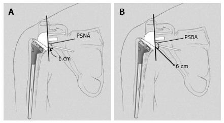
Figure 5 Illustration of measurement of the prosthesis-scapular neck angle and the prosthesis-scapular bone angle.
A: The prosthesis-scapular neck angle is the angle between a line from superior to inferior along the glenoid baseplate and a line from the most inferior point of the baseplate’s prosthesis-bone interface to a point 1 cm medially along the inferior scapular neck; B: The prosthesis-scapular bone angle uses a point 6 cm medial along the scapular border to draw the second line. PSNA: Prosthesis-scapular neck angle; PSBA: Prosthesis-scapular bone angle. Reprinted with permission from Kempton et al[24], Figure 3.
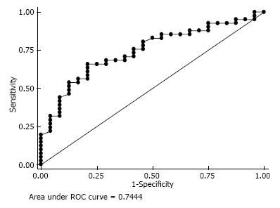
Figure 6 The receiver operating characteristic curve reveals the sensitivity and specificity for predicting the inferior glenoid tilt.
- Citation: Huri G, Familiari F, Salari N, Petersen SA, Doral MN, McFarland EG. Prosthetic design of reverse shoulder arthroplasty contributes to scapular notching and instability. World J Orthop 2016; 7(11): 738-745
- URL: https://www.wjgnet.com/2218-5836/full/v7/i11/738.htm
- DOI: https://dx.doi.org/10.5312/wjo.v7.i11.738


