Copyright
©The Author(s) 2021.
World J Orthop. May 18, 2021; 12(5): 270-291
Published online May 18, 2021. doi: 10.5312/wjo.v12.i5.270
Published online May 18, 2021. doi: 10.5312/wjo.v12.i5.270
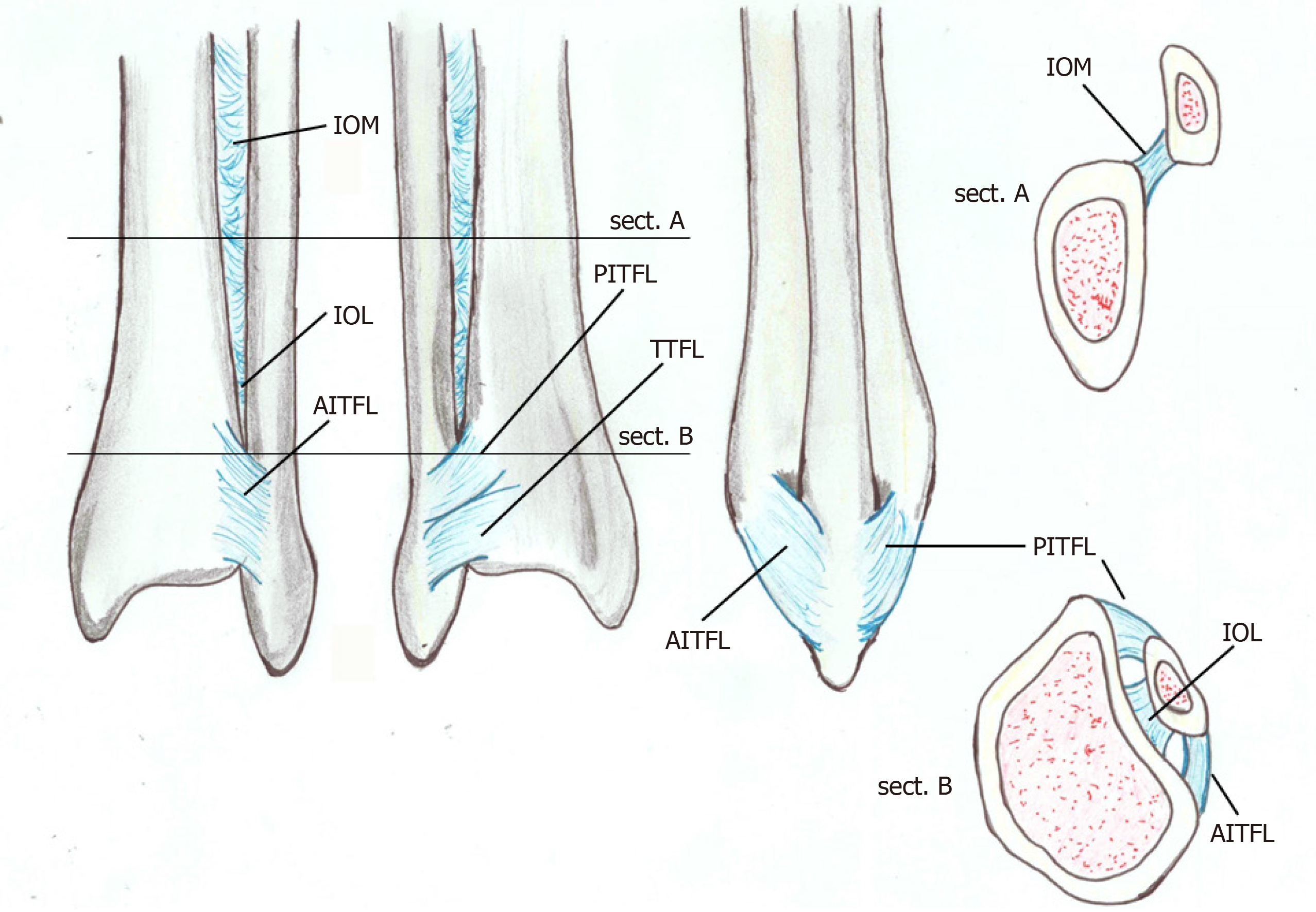
Figure 1 Anatomy of the distal tibiofibular syndesmosis: anterior view, posterior view, lateral view and proximal and distal coronal view.
AITFL: Anterior inferior tibiofibular ligament; IOL: Interosseous ligament; IOM: Interosseous membrane; PITFL: Posterior inferior tibiofibular ligament; TTFL: Transverse tibiofibular ligament.
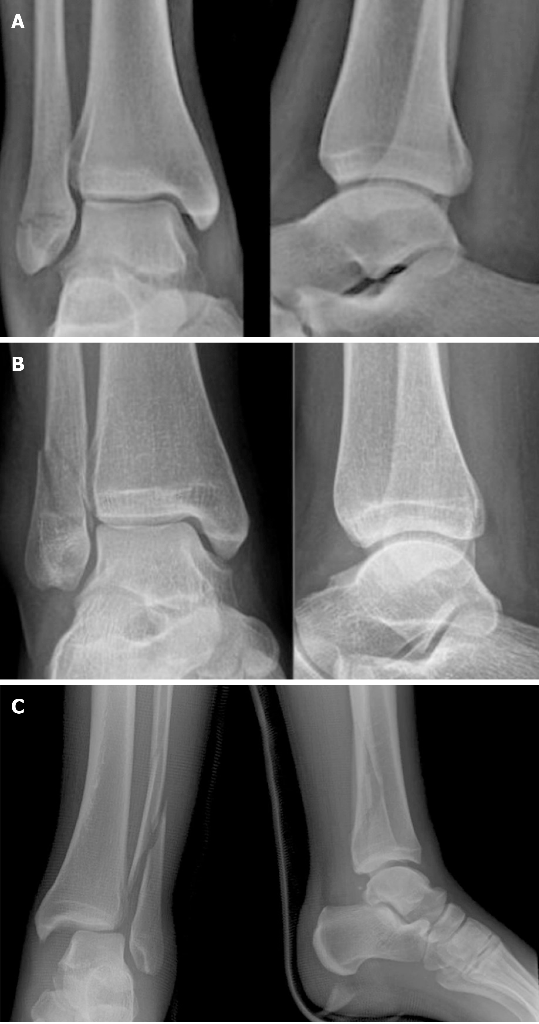
Figure 2 Radiographs representing the three types of ankle fractures according to Danis-Weber.
A: Infrasyndesmotic; B: Trans-syndesmotic; C: Suprasyndesmotic.
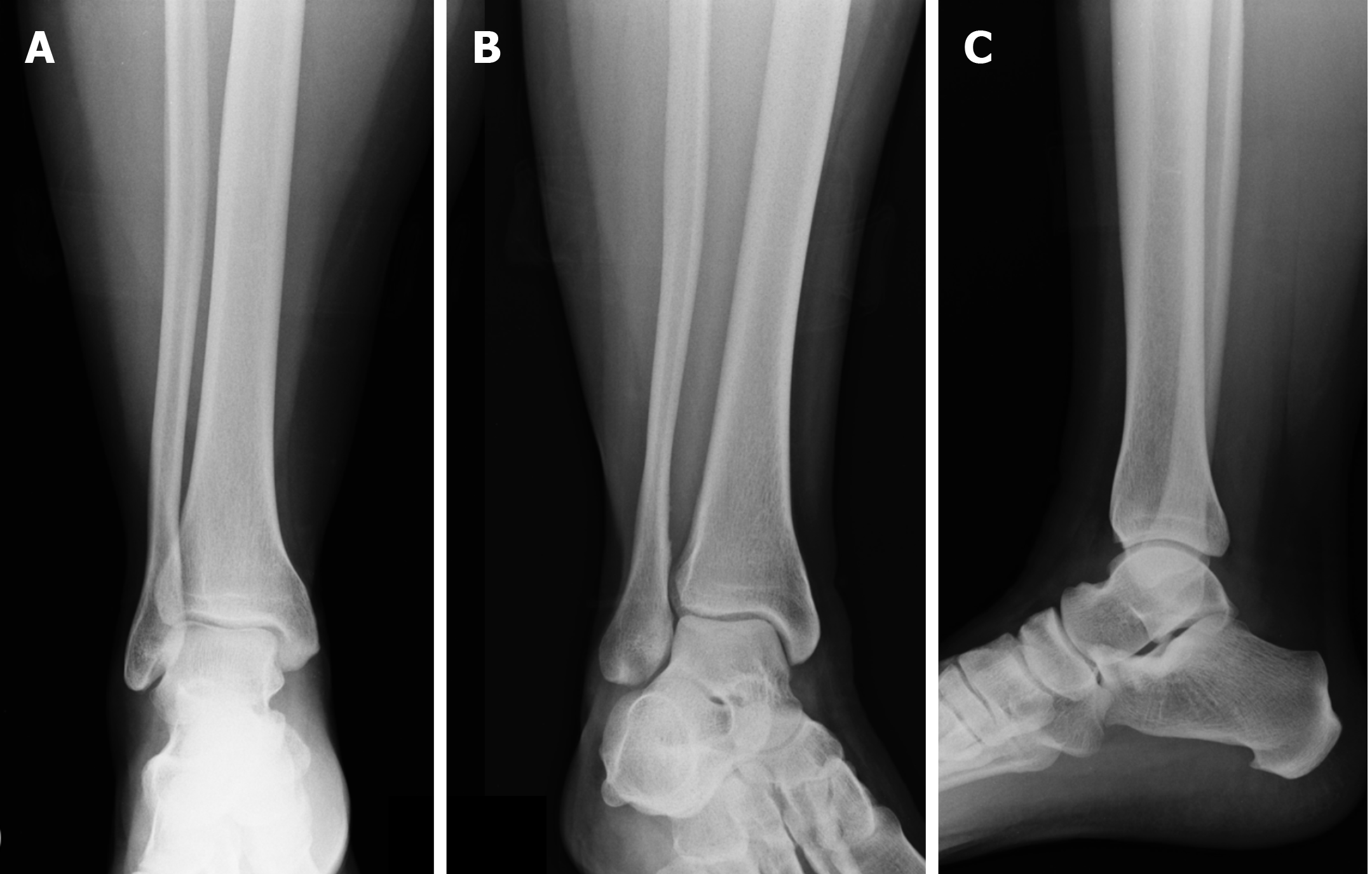
Figure 3 X-ray of the right ankle: standard projections.
A: Anteroposterior; B: Mortise; C: Laterolateral views.
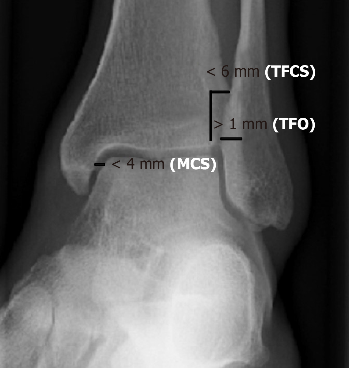
Figure 4 Normal values of tibiofibular clear space, tibiofibular overlap and medial clear space in left ankle mortise projection.
MCS: Medial clear space; TFCS: Tibiofibular clear space; TFO: Tibiofibular overlap.
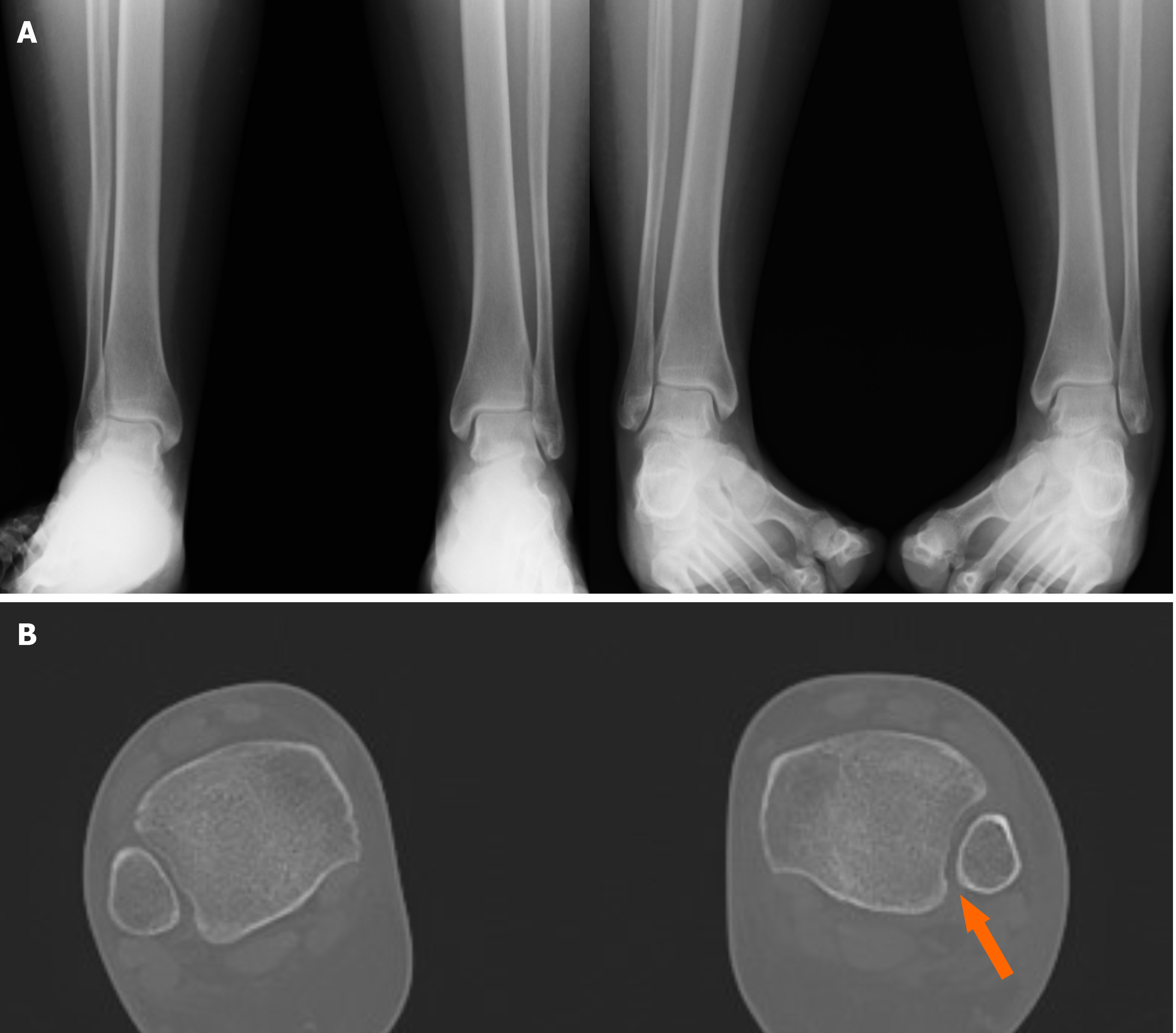
Figure 5 Suspect of a left syndesmotic lesion.
A: Comparative X-ray and based on the measurements of the tibiofibular clear space, tibiofibular overlap and medial clear space, the exam was considered negative; B: Computed tomography assessment showed a difference (> 2 mm) between both sides (arrow), demonstrating the presence of a syndesmotic lesion.
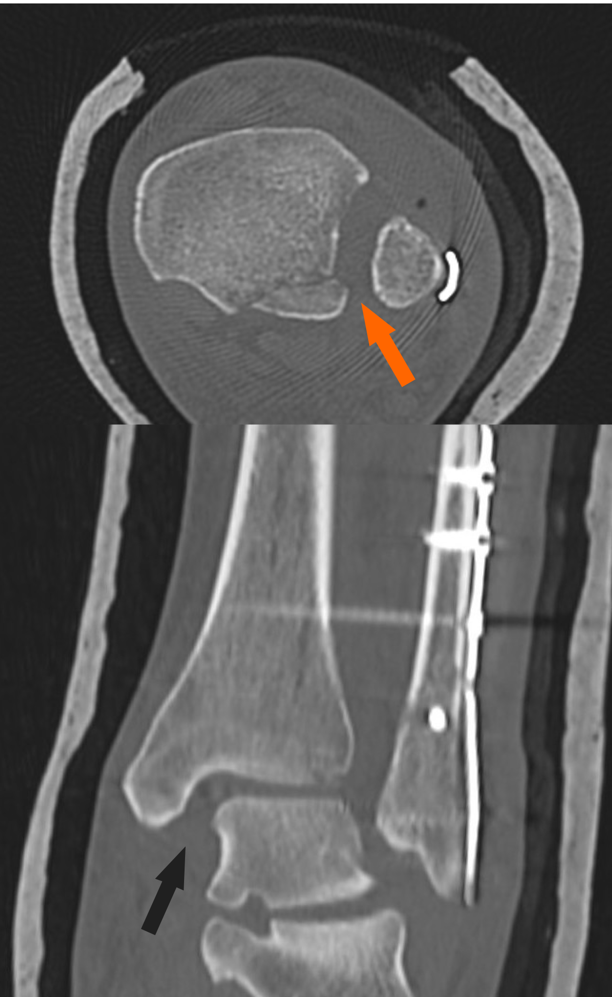
Figure 6 Postoperative computed tomography scans of a syndesmotic lesion showing a widened tibiofibular space (arrows) indicative of an inadequate reduction.
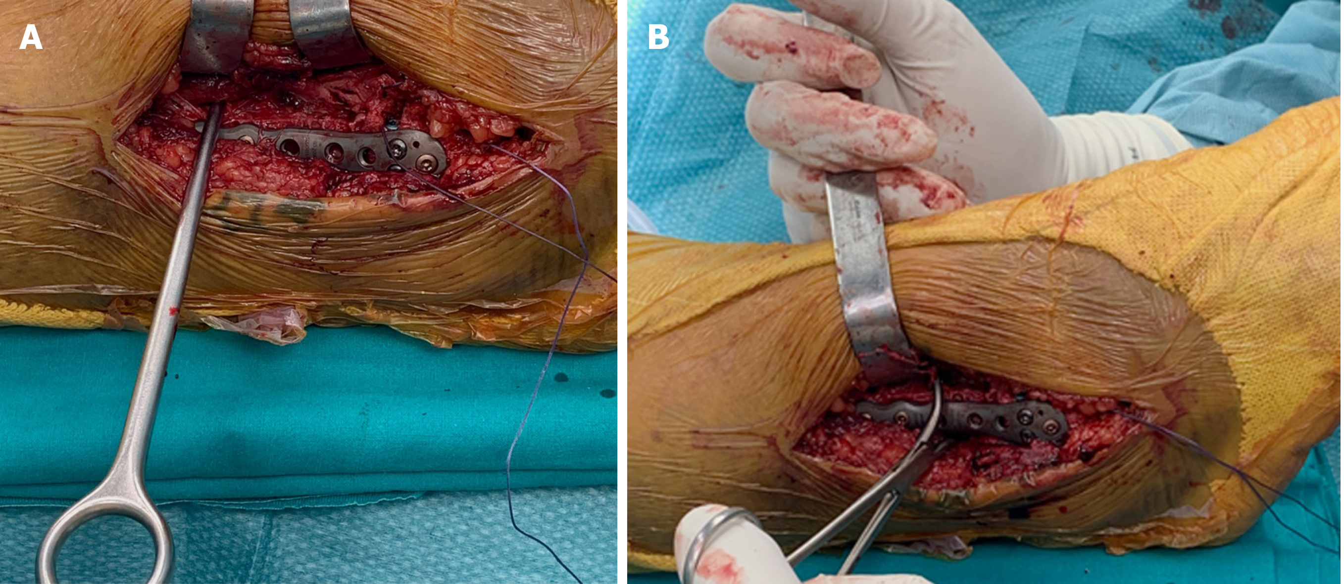
Figure 7 Intraoperative view.
A: Modified Cotton test with hook; B: Modified Cotton test with reduction clamp.
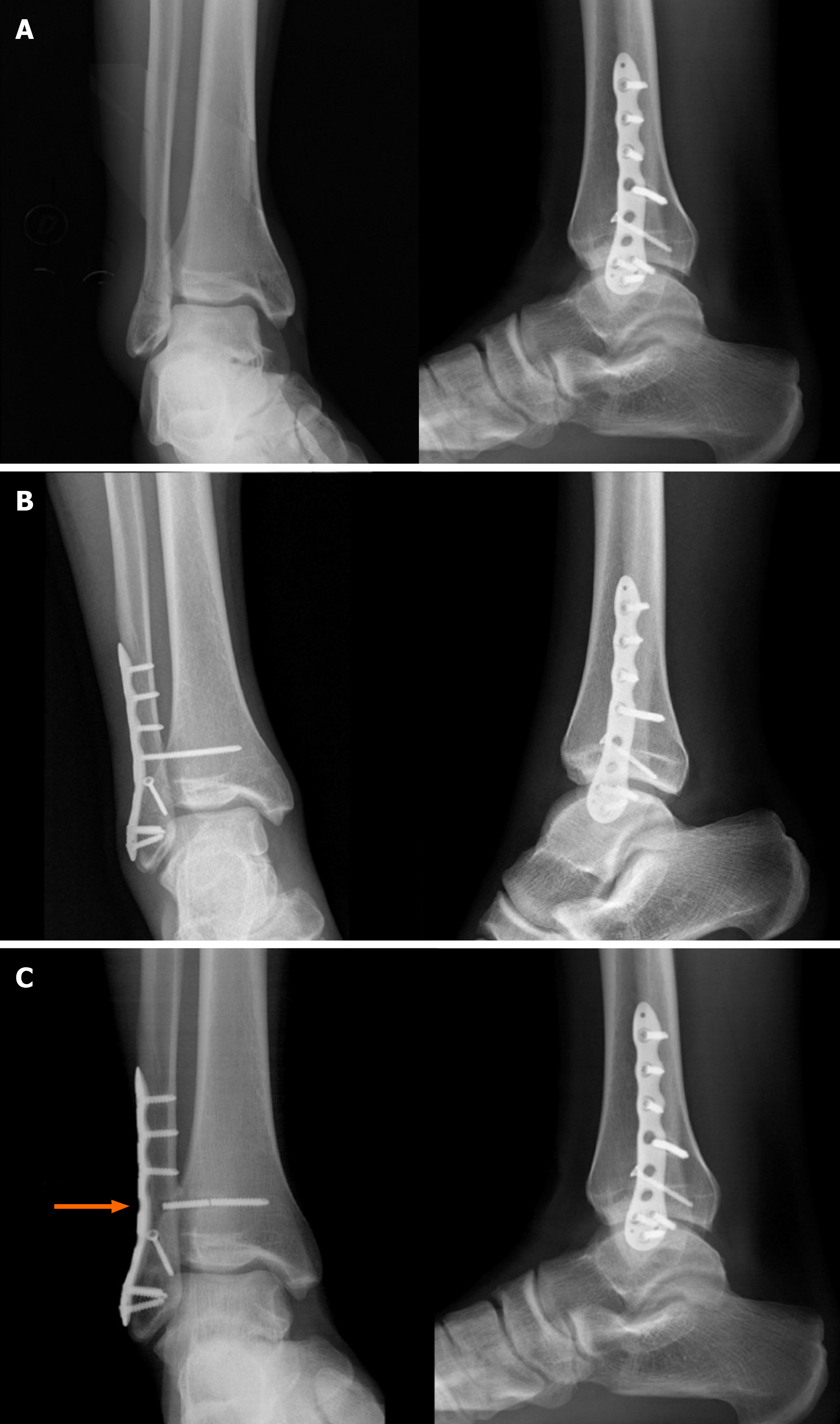
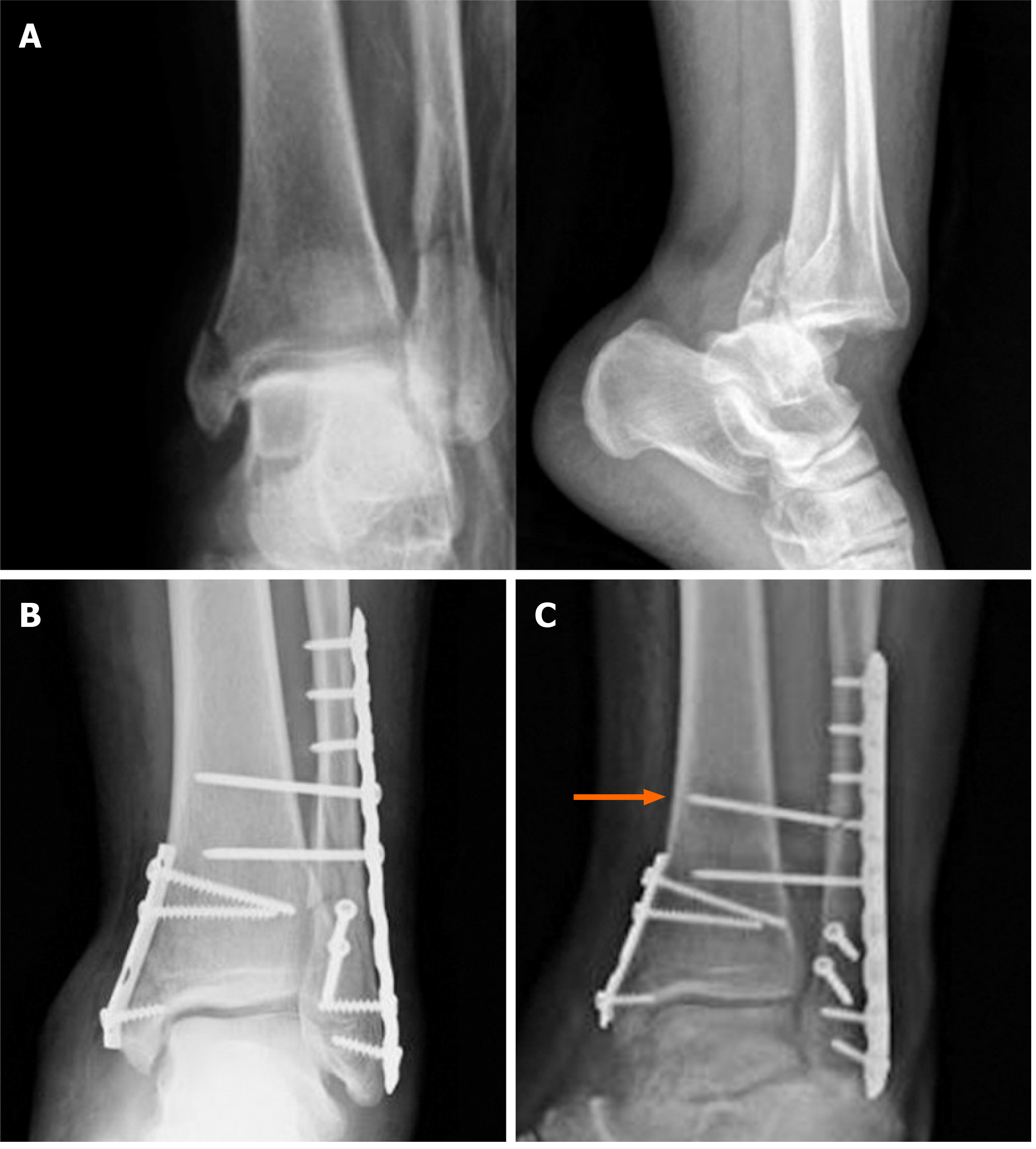
Figure 8 Type B ankle fracture.
A: Preoperative X-rays; B: Radiographs 1 mo after surgery; C: Radiographs 2 mo after surgery following removal of the screw that was discovered broken (arrow) during the second procedure.
Figure 9 Type C ankle fracture and dislocation.
A: Preoperative X-rays; B: Postoperative X-rays; C: Radiographs performed 3 mo after trauma with breakage of the proximal intersyndesmotic screw (arrow).
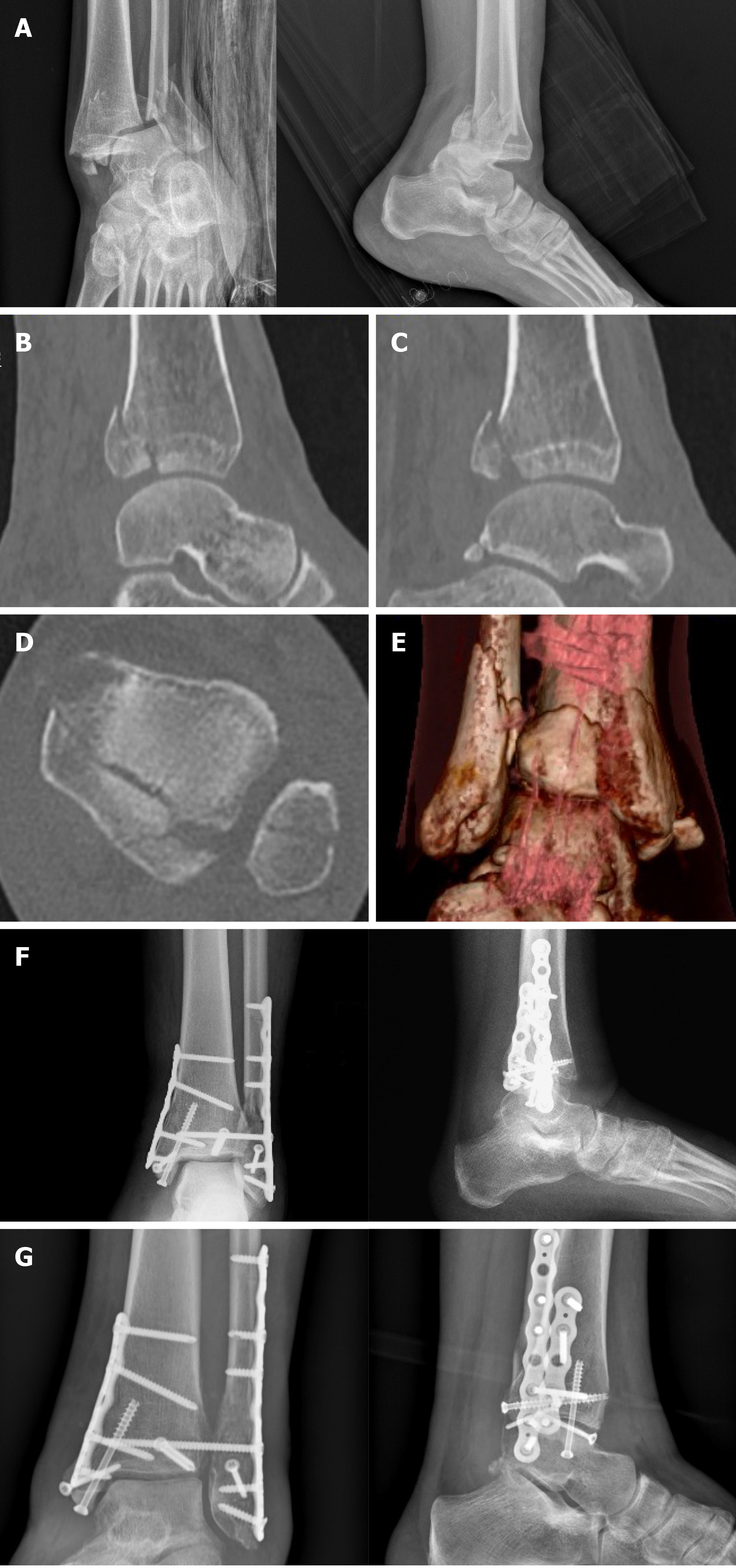
Figure 10 Trimalleolar right ankle fracture associated with dislocation.
A: Preoperative X-rays; B and C: Computed tomography sagittal views with posterior malleolar fracture [tibial portion (B) and peroneal portion (C)]; D: Computed tomography axial view; E: Three dimensional computed tomography; F: Postoperative radiographs after fixation of the fibula and of the lateral part of the posterior malleolus with a P-A screw through a posterolateral approach and of the medial malleolus and of the tibial part of the posterior malleolus through a posteromedial approach (plates and screws); G: X-rays 8 mo following surgery with consolidation.
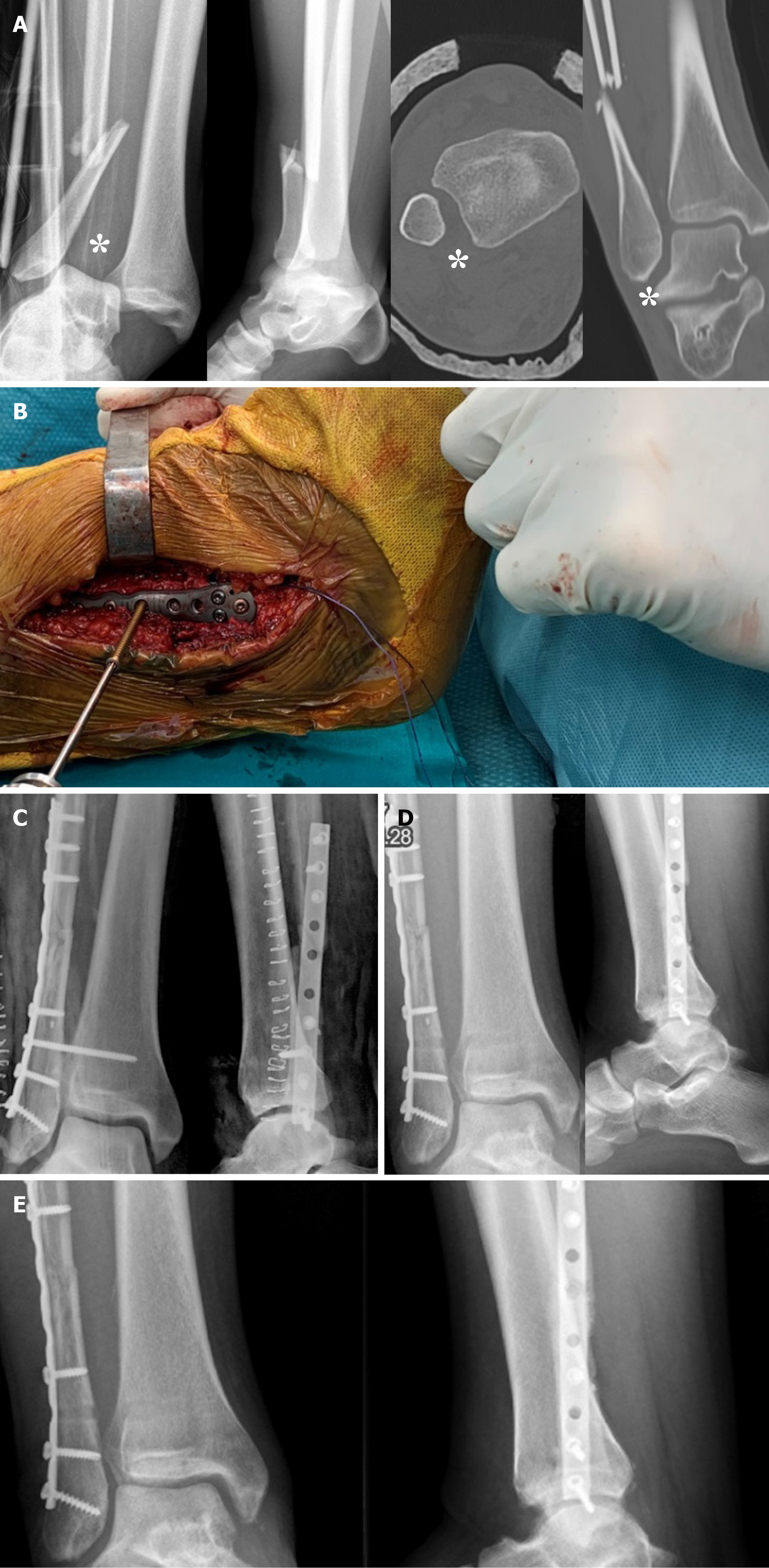
Figure 11 Type C ankle fracture.
A: Preoperative X-rays and computed tomography performed after closed reduction with diastasis (asterisks); B: Intraoperative positioning of the 3.5 mm intersyndesmotic screw with the foot positioned at 90° of dorsiflexion; C: Postoperative radiographs; D: Removal of the screw 2 mo after surgery; E: Views 6 mo after trauma with fracture consolidated.
- Citation: Pogliacomi F, De Filippo M, Casalini D, Longhi A, Tacci F, Perotta R, Pagnini F, Tocco S, Ceccarelli F. Acute syndesmotic injuries in ankle fractures: From diagnosis to treatment and current concepts. World J Orthop 2021; 12(5): 270-291
- URL: https://www.wjgnet.com/2218-5836/full/v12/i5/270.htm
- DOI: https://dx.doi.org/10.5312/wjo.v12.i5.270


