Copyright
©The Author(s) 2015.
World J Radiol. Dec 28, 2015; 7(12): 521-530
Published online Dec 28, 2015. doi: 10.4329/wjr.v7.i12.521
Published online Dec 28, 2015. doi: 10.4329/wjr.v7.i12.521
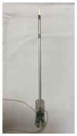
Figure 1 Trans-urethral ultrasound therapy probe.
Rigid, water-cooled trans-urethral ultrasound applicator with 5 mm (15 French) diameter and eight transducer elements (4 mm × 5 mm/element).
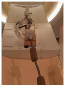
Figure 2 Magnetic resonance imaging-compatible ultrasound therapy device.
Set-up of the trans-urethral ultrasound applicator on the MRI patient table with control cables, and motor unit to control the rotation of the ultrasound transducer. MRI: Magnetic resonance imaging.
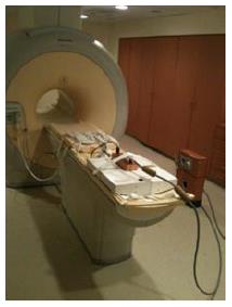
Figure 3 Equipment integration for magnetic resonance imaging-guided ultrasound therapy.
Frontal oblique view of the 3T Philips MRI scanner with an 8-channel cardiac MR coil on the anterior part of the scanner table and ultrasound transducer on the posterior part of scanner table. MRI: Magnetic resonance imaging.
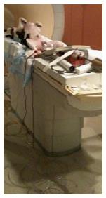
Figure 4 Canine positioning for magnetic resonance imaging-guided ultrasound therapy.
Positioning of a canine in supine orientation on the patient table and preparation for the placement of the transurethral ultrasound transducer in the canine prostate.
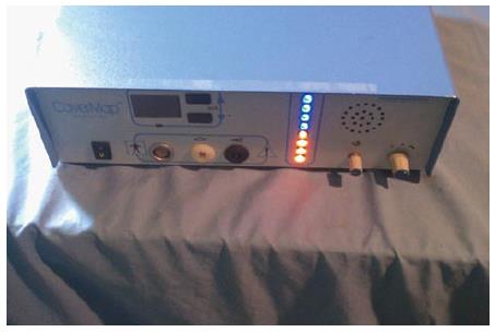
Figure 5 The CaverMap Surgical Aid nerve stimulator control unit.
Device control unit with connectors for the stimulation needle, display of the applied current in mA, and light-emitting diode display (blue and red) to visualize tumescence response on an ordinal scale.
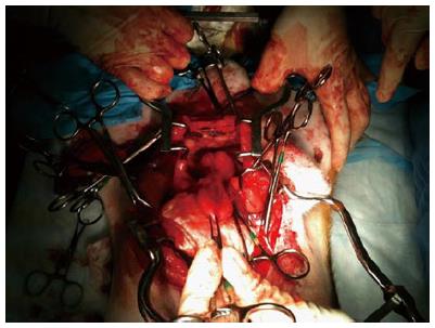
Figure 6 Surgical preparation of the canine prostate for nerve stimulation of the cavernosal nerves.
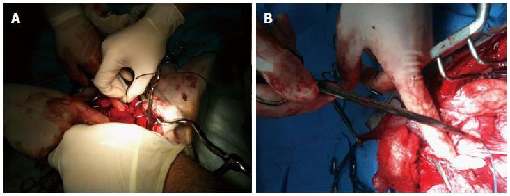
Figure 7 Placement of the CaverMap Surgical Aid nerve stimulator (A and B).
Intrasurgical placement of the stimulation needle of the CaverMap Surgical Aid nerve stimulator close to the cavernosal nerves of the canine prostate.
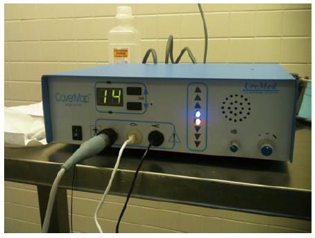
Figure 8 The CaverMap Surgical Aid nerve stimulator display.
Control unit and display of the CaverMap Surgical Aid nerve stimulator to measure tumescence response on an ordinal scale intraoperatively. Below the digital display are the connectors for the probe handle, the tumescence sensor, and the lead for connecting the tumescence sensor to the control unit. The electric current for stimulation is emitted by the probe tip.
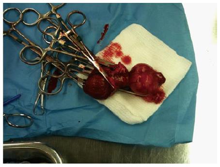
Figure 9 Explanted canine prostate and bladder after prostatectomy.
Figure 10 Histology of treated canine prostate.
Series of histological slides of a canine prostate after H and E staining show ultrasound ablation zones and hemorrhage.
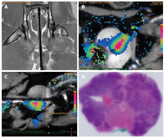
Figure 11 Example images of planning, treatment, and histological outcome.
A: Coronal MR image of the intra-urethral catheter placement in the canine prostate for treatment planning with the canine in supine position: The ultrasound applicator is forwarded in the penile urethra to the prostate; B: Color-coded axial temperature map overlaid on the corresponding anatomical MR image demonstrates the typical temperature distribution post ultrasound treatment. Proton Resonance Frequency Shift measurements with a FFE-EPI imaging sequence were used for temperature monitoring and control; C: Sagittal temperature map during ultrasound treatment; D: Histological slide of the canine prostate in haematoxylin and eosin staining to evaluate ultrasound treatment effects. MR: Magnetic resonance; FFE: Fast-field echo.
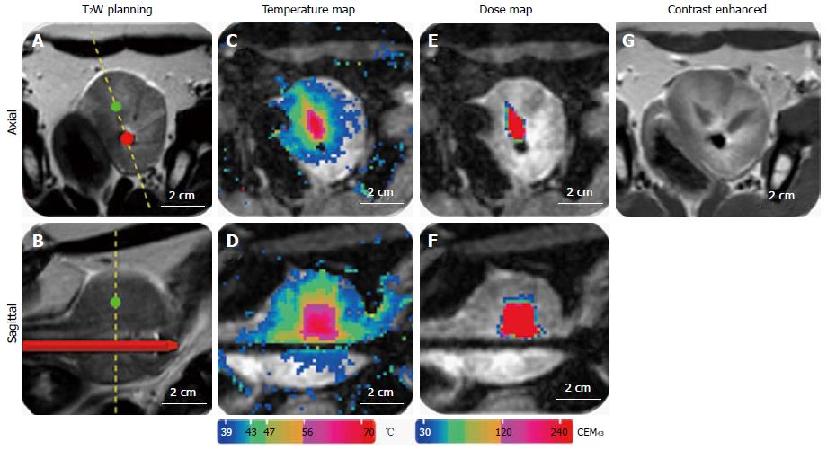
Figure 12 Representative images of magnetic resonance imaging-guidance.
A: T2-weighted image for positioning and treatment planning in axial and sagittal orientation (B); C: MR temperature map during ultrasound treatment in axial and sagittal orientation (D); E: MR dose map during ultrasound treatment in axial and sagittal orientation (F); G: Contrast enhanced T1-weighted image after ultrasound treatment. MR: Magnetic resonance.
- Citation: Sammet S, Partanen A, Yousuf A, Sammet CL, Ward EV, Wardrip C, Niekrasz M, Antic T, Razmaria A, Farahani K, Sokka S, Karczmar G, Oto A. Cavernosal nerve functionality evaluation after magnetic resonance imaging-guided transurethral ultrasound treatment of the prostate. World J Radiol 2015; 7(12): 521-530
- URL: https://www.wjgnet.com/1949-8470/full/v7/i12/521.htm
- DOI: https://dx.doi.org/10.4329/wjr.v7.i12.521


