Published online Nov 26, 2015. doi: 10.4330/wjc.v7.i11.754
Peer-review started: March 26, 2015
First decision: May 13, 2015
Revised: September 24, 2015
Accepted: October 16, 2015
Article in press: October 19, 2015
Published online: November 26, 2015
Processing time: 250 Days and 5.7 Hours
Endocardial access to the left atrium is commonly achieved to treat patients with atrial fibrillation, using different device delivery systems for cardiac ablation. But the large variation in human anatomy presses the limits of existing medical devices. In this unique study, we directly visualized the device-tissue interface in fresh reanimated human hearts using Visible Heart® methodologies. Our goal was to better understand any opportunities to improve therapeutic approaches. The visual images obtained in this study (also featured in this article) allow a more intimate grasp of the key steps required in various ablation procedures, as well as some limitations of current device designs. These images show the potential risks of conducting transseptal punctures and the difficulties of placing catheter tips in certain scenarios (e.g., when creating circumferential lesions); they also demonstrate potential problems that could occur while attempting to place catheter tips on such anatomies like the mitral isthmus. In our analysis of these images, we focus on where enhancements are needed to refine device functionality.
Core tip: Visible Heart® methodologies are utilized to directly visualize a functional human heart anatomy and key steps in the cardiac ablation procedure to emphasize limitations of current device delivery systems. Specifically, these images illustrate potential risks of transseptal punctures as well as the challenges faced by clinicians when placing catheter tips in certain scenarios, considering the wide variation in human anatomy. The focus is on where enhancements are needed to refine device functionality and improve therapeutic approaches.
- Citation: Benscoter MA, Iaizzo PA. Visualization of catheter ablation for atrial fibrillation: Impact of devices and anatomy. World J Cardiol 2015; 7(11): 754-764
- URL: https://www.wjgnet.com/1949-8462/full/v7/i11/754.htm
- DOI: https://dx.doi.org/10.4330/wjc.v7.i11.754
For many years, ablation (either radiofrequency or cryogenic) has been used to treat patients with atrial fibrillation (AF)[1-3]. But variations in cardiac anatomy have consistently influenced therapeutic success[4-8]. Different medical device designs have been developed for creating effective lesions in such varied anatomic structures[9-12]. However, in order to apply therapies for left atrium (LA) targets, navigation is first required into the right atrium (RA) and then across the septum.
Ablating the anatomic locations within the left heart was initially made feasible by a modified Cox’s maze procedure[13-16]. In such a procedure, each step requires an intimate understanding of the endocardial anatomy[17]. Importantly, the inappropriate placement of devices in any ablation procedure can result in significant unintended consequences, including the creation of ineffective lesions (no transmurality), the need for subsequent ablation procedures, and/or cardiac tamponade during transseptal punctures[18-20]. In an effort to reduce the incidence of such unintended consequences, ablation is commonly performed with the assistance of imaging tools such as fluoroscopy or echocardiography. Imaging tools not only help eliminate unintended consequences such as perforation, but also help ensure occlusion of pulmonary veins (PVs). In addition, the use of fluoroscopy, angiography, and noncontact mapping has improved the quality of the images[21]. However, no imaging method allows one to directly visualize the device-tissue interface or to take into consideration the impact of accuracy on heart rhythm[21,22].
In this unique study, we used Visible Heart® methods to directly visualize the device-tissue interface in fresh human hearts reanimated in a clear Krebs-Henseleit buffer (Sigma-Aldrich Corporation, St. Louis, MO, United States), as previously described[22,23]. Our goal was to better understand any opportunities to improve therapeutic approaches during the key steps of various ablations procedures. The visual images obtained in our study (and featured in this article) allow a more intimate grasp of the steps required as well as any limitations of current device designs.
In particular, the images reveal the interaction of ablation technology with human tissue, providing a sense of the spatial relationship between the device and anatomic structures. In our analysis of these images, we focused on where enhancements are needed to refine device functionality. For purposes of analysis, we separated the key steps of ablation procedures into 3 distinct image sets, based on the device used and the anatomy: (1) navigating the RA; (2) conducting transseptal punctures from the RA to the LA; and (3) creating lesions and reaching the key anatomic locations in the LA with different types of ablation devices. Delineating the limitations of current devices and pinpointing the major anatomic challenges should prove to be of great importance for both practicing physicians and medical device designers[23].
Success in navigating the RA has been limited, given the challenging anatomies of key RA structures combined with the limitations of current device designs. Endocardial cardiac ablations of the atria commonly originate via access from the inferior vena cava (IVC). An introducer, at the groin, is inserted into the femoral vein and then advanced into the RA. The IVC serves as a low-pressure return path of deoxygenated blood to the RA. Thus, the IVC is a suitable starting point for endocardial procedures because it eliminates risks associated with device introduction. Key ablation procedure structures in the RA include the fossa ovalis (FO), coronary sinus (CS), and right atrial appendage (RAA).
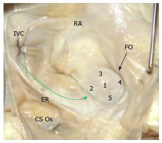
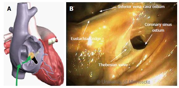
The FO serves as the access point for ablation of the LA. As devices enter the RA, the Eustachian valve of the IVC forms a bridge between the IVC and the Eustachian ridge (ER) (Figure 1).
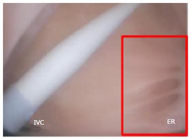
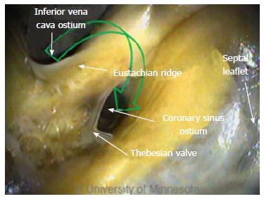
The FO is also a structure that causes devices to bind or become lodged, and device tips can catch on the compliant membrane of the valve[24-26]. Because the FO and the IVC are located on the superior aspect of the ER, the ER can serve as a guide to facilitate device delivery to the FO, allowing the device to glide along the valve and onto the ER (Figure 2B and C).
The ER is a prominent rise between the FO and the CS ostium (Os)[27-29]. The superior and posterior margins of the FO are enfolded to produce the prominent muscular protrusion on the endocardial surface. The FO lies next to the aorta, in some cases making transseptal punctures difficult[30]. Bordered by septal tissue and the ER, the FO is typically slightly recessed (Figure 2B and C). These structures can either facilitate or inhibit the operation of a medical device, either directing it in the intended direction or preventing it from being placed in the desired location.
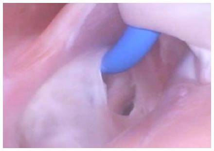
Current catheter delivery systems often face challenges in reaching the FO and conducting transseptal punctures. Pectinated muscles adjoin the ER, which itself is pronounced and moves with each contraction. The pectinated muscles adjacent to the FO are composed of undulations that are capable of restraining the tip of a dilator or catheter (Figure 3). Dilator tip dimensions are sized to only allow a transseptal needle to pass. This small tip size also increases the chance of binding in these muscles if the tip is placed incorrectly.
During transseptal punctures, the FO is manipulated extensively. Both its size and thickness contribute to changes in the amount of compliance when force is applied (Figure 4). A large amount of compliance in the FO, coupled with a lack of compliance in the much thicker septal wall, can result in concentration of the transseptal force on the FO.
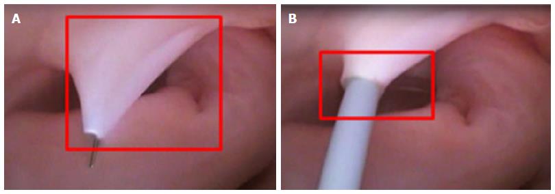
Dilator tips enable practitioners to confirm anatomic location by tenting the FO. Once tenting is achieved, a transseptal needle can be advanced through the FO (Figure 5A and B). The large amount of tenting that is usually required and the compliance of the membrane draw into question how much force the FO is able to tolerate before the procedure fails. Though necessary to perform transseptal punctures, FO tenting-combined with excess extension of the transseptal needle tip into the LA - can result in cardiac tamponade.
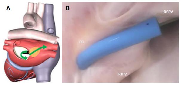
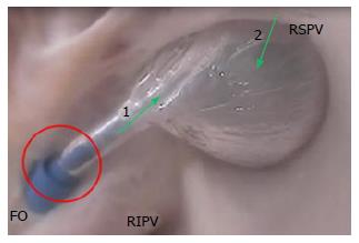
The very close proximity of the FO to both the right superior pulmonary vein and the right inferior pulmonary vein makes it challenging to reorient device tips after transseptal punctures (Figure 6).
Devices whose total deflection is limited, or whose deflection is located more proximally in the shaft, result in tip changes that make it nearly impossible to orient the device in a way that facilitates catheter introduction into the right PVs. Consequently, the FO needs to be manipulated more. Additionally, an incorrect puncture site location can increase the difficulty of introducing a catheter into the right PVs.
Once a transseptal puncture is complete, the tissue is stretched over the outside diameter of the dilator and onto the outside diameter of the sheath (Figure 5B). This transfer of force, the overall diameter of the sheath, and manipulation of the device in the LA can all contribute to the possibility of tearing the FO. As the sheath is deflected and the device is introduced into the LA, the resulting forces on the sheath push and pull the FO. If these forces become excessive, the FO can tear (Figure 7).
This step in the procedure prompts additional consideration of the use of the transseptal needle in the LA. The transseptal needle extends beyond the tip of the dilator. The amount of extension is dictated by the interference fit of the diameter on the needle shaft to the internal diameter reducer in the dilator tip. Given the large amount of needle extension and the relative thickness of the FO, future device designs must improve the needle tip to reduce the risk of cardiac tamponade, while still preserving the ability to achieve successful punctures. Clearly, anatomic variations can have an impact on the ability to conduct transseptal punctures as well as possible complications.
Such variability in anatomic structures - combined with current device limitations in sheath size and in needle, length, and deflection capabilities - will require continued advancements in order to decrease the risk to patients. Device developers must continue to collaborate with electrophysiologists. A partnership between engineers and health care providers is critical for improving patient outcomes.
Arrhythmia ablation procedures commonly involve the CS[6,31]. Its ostium is located on the opposing side of the ER. In addition, the thebesian valve is located at the CS ostium (Figure 8). Inferior to the CS ostium, anatomic structures can be of various shapes and sizes[32].
Clearly, anatomic factors can increase the complexity of device delivery. The CS ostium resides in a deep pocket that is bordered by the ER, making catheter tip placement challenging. The location of the CS ostium relative to the IVC, along with the size of the ostium, can also present challenges.
To enter the CS, devices must have a high degree of deflection; furthermore, the region of deflection must have a small radius. With devices whose deflection is located more proximally in a stiff shaft and whose diameter is 8-Fr or larger, it will be more difficult to orient the tip so that it aligns with the CS ostium (Figure 9). Further design work is needed to develop devices that can deflect in a small radius, allowing the catheter tip to be oriented in such a way that it can align with the CS ostium.
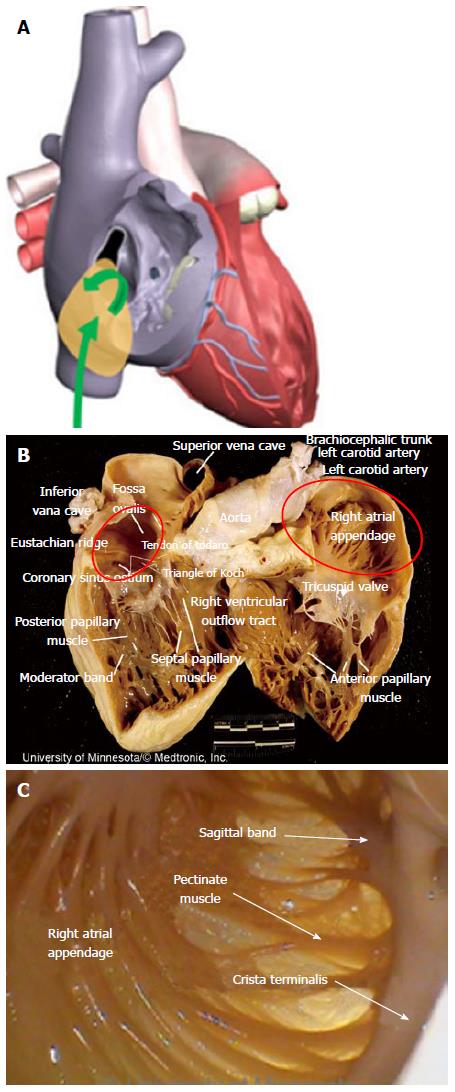
Right atrial ablation is required in instances of AF in which the cycle length recorded in the RAA is shorter than is the cycle length recorded in the left atrial appendage (LAA). The RAA location near the ostium of the IVC prompts the need to deflect devices (Figure 10A). The appendage can be a large structure; it is composed of very thin tissue as well as pectinated muscle and a sagittal band (Figure 10B and C).
Given the thin tissue of these anatomic structures, devices need to have very smooth tips that do not focus force into a point. With devices that have a rigid shaft, the risk of perforating the RAA is greater, because of the higher transfer of force. In contrast, with devices that have a compliant tip at the distal end, the tip can bend, thereby lessening the chance of perforating the RAA.
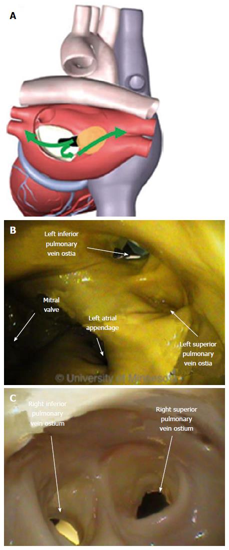
The LA has a venous component, along with a vestibule and an appendage. The additional 4 venous orifices serve as corners to the atrium. The vestibule surrounds the mitral ostium. The LAA is typically a small extension that originates adjacent to the mitral valve annulus and the left PVs.
In the atrial areas, the anterior wall behind the aorta is commonly thin and can be torn during transseptal punctures[33]. The thicker parts of the LA are on the superior wall[34]. The ostium of the right PVs are adjacent to the plane of the atrial septum. The tissue that makes this transition is smooth. The target of PV isolation is a muscular sleeve that extends into each vein and ends inside the sleeve; the role of the sleeve has been reviewed in other studies[35,36]. The organization of electrical activity from the PV is well known[37,38].
The smooth wall of the LA facilitates a uniform drag of the catheter tip against the tissue. The size of the LA is conducive to catheter tip placement against the tissue surface[27]. But the formation of a small gap is possible; complex cardiac navigation systems do provide some guidance as to gap location, yet it might not be sufficient.
LA ablation can occur in a number of different locations and can be prompted by continuous electrical activity, with a minimum duration of 100 ms[39] and either fractionated or fragmented electrical activity[40].
Pulmonary vein isolation is currently considered as a key step in treating patients with all forms of AF. Of note, the muscle sleeves in the ostial opening of all 4 PVs emit ectopic beats. Electrical isolation of each vein is now the standard of care for treating AF, using either cryogenic or radiofrequency ablation[28-30]. In electrical isolation procedures, both ablation and diagnostic devices are used around and inside the PVs including guidewires, balloons, diagnostic catheters, and focal ablation catheters.
The ostia of the right PVs are adjacent to the FO. The ostial opening of the PV is a smooth surface. The close proximity of the PV ostia to the FO, and the sharp angle between them, make it difficult to orient a catheter through the puncture site and into the PV (Figure 11).
The ostia can comprise ridges and are adjacent to each other on opposing sides of the atrium. The shape and orientation of the PV can vary; other anatomic structures can be atypical. Variations can include differences in ostial size and the existence of a common shared ostium. All of these factors can affect the effectiveness of the devices used to electrically isolate the tissue.
The PVs interface with guidewires, sheaths, balloons, and focal ablation catheters. The location of the transseptal puncture can have a dramatic effect on the ability to place the catheter tip in the ostium of the PV, especially because the distance from the FO to the ostium is short. In addition, the orientation of the opening of the PV is directed in a way that can result in the need to twist the guidewire to allow it to migrate inside the PV (Figure 12A). This anatomic orientation of the FO and the PV illustrates the importance of a sheath that has a small radius of deflection at the tip in order to facilitate guidewire insertion.
Catheter placement into the PV is also affected by the contour of the catheter tip. The angle of the catheter’s approach might require anatomic guidance to properly position the tip (Figure 12B). This device-tissue interface shows the importance of a smooth, contoured tip.
The complete insertion of the ablation catheter is affected by its size and by the size of the atrium. The proximity of the FO to the PV can limit the ability to have both the sheath and the catheter in the chamber (Figure 12C). Limiting the distance of the therapeutic region of the catheter would provide greater latitude for use of the entire system in the atrium. Operation of these devices on the right side of the atrium is one of the more challenging steps of the procedure.
Performing the same steps on the left side of the atrium requires different device performance. The orientation of the FO to the left PV ostia (as compared with the right side of the atrium) is more conducive to device delivery. Guidewire introduction is typically facilitated by the nearly linear orientation of the FO to the PV ostium (Figure 13A), which allows the guidewire to be placed and lodged in the PV (Figure 13B).
The alignment of the FO and left PVs allows for easy catheter introduction into the LA and sufficient room to operate the device, thereby reducing the stress on the FO and lessening the demands on the sheath (Figure 13C). For balloon-based devices, which require more area to operate than do focal ablation catheters, the alignment of the FO and left PVs is of particular importance.
Once the catheter is delivered into the PVs, therapy delivery remains challenging. For example, balloon-based therapeutic devices are larger, with only a limited amount of deflection ability, so they require more room to operate. Given the orientation of the transseptal puncture to the ostium of the PV, the balloon is able to fully occlude the vein. However, uniform cooling may not be achieved, because the balloon’s orientation is limited by the FO’s orientation to the PV’s muscular sleeve (Figure 14).
These anatomic challenges accentuate the importance of having an acute distal deflection segment on the ablation device, in order to improve catheter tip orientation to, and alignment with, the PV ostium. Such challenges also jeopardize the ability of the sheath to maintain its placement in the LA. Decreasing the length of the distance between the distal tip of the sheath and the proximal end of the balloon would allow more sheath to be retained in the LA. The sheath must have a very distal deflection control with an acute radius of deflection. The smooth wall of the atrium facilitates placement of the ablation catheter.
If additional lesions are necessary beyond PV isolation, they can be created in the LA in the form of a linear lesion along the roofline or a mitral isthmus (MI) lesion, or via ablation of the LAA.
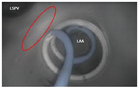
Many times, the LAA is a site for the deposition of thrombus. A stroke is a possibility if the thrombus is able to dislodge and travel to a part of the vasculature that supplies blood to the brain. The LAA is oriented on the opposing side of the LA from the FO, making device delivery less challenging (Figure 15A).
For achieving and retaining device placement, the opening of the LAA can be challenging. The ability to place a focal ablation device at the ostial opening is complicated by the presence of prominent ridges in the ostial area of the LAA. Focal devices for performing point-by-point ablation around the opening are difficult to operate. Alternatively, devices that encircle the LAA, or that occlude it, preclude the need to create point-by-point lesions and remove the complexity of attempting to place a catheter tip on a ridge structure.
Devices that deploy into the LAA and then place the therapeutic region at the opening are able to encircle the opening (Figure 16). Focal ablation devices need the ability to apply sufficient force on the tissue for lesion generation, without slipping into the pectinated muscles of the LAA interior.
Dynamically shaped ablation devices that could occlude the LAA would have an advantage, as they might be able to maintain position and sufficient force for lesion generation.
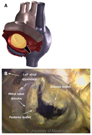
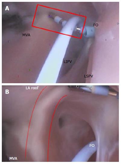
The MI is a region of tissue that borders the annulus of the mitral valve and the LAA, and then rises over the ridge toward the left PV (Figure 17A). This is a common area to create a contiguous lesion in which it helps to terminate conduction patterns in patients with AF in whom PV isolation is not sufficient[27,31,32].
The creation of the MI or roofline linear lesion is affected by even a minor amount of anatomic movement of the MI with each contraction, making catheter tip placement on the ridge difficult. Any anatomic movement changes the force on the catheter tip and can contribute, at times, to a temporary loss of sufficient contact for lesion creation. The ability to maintain tissue contact is a byproduct of the amount of force on the catheter tip. For MI linear lesion creation, given the orientation of the FO in relation to the mitral valve annulus (MVA), the catheter tip must be able to reach to the MVA, and the deflection must be able to place force on the catheter tip (Figure 17B). The presence of a ridge is an additional complicating factor; the shape of the ridge can be pointed, making it difficult for the catheter to be placed on it.
To ensure necessary contact when creating a linear lesion, a focal catheter may be used against a supporting structure, such as another catheter (Figure 18A) or the wall of the atrium (Figure 18B).
A focal ablation catheter has the advantage of adaptability. This device design could be extended to include repositioning of electrodes, softening of the tip, and better deflection capabilities - all of which could widen application across an array of atrial anatomies, resulting in an improvement in energy delivery.
Understanding how ablation devices interface with tissue and anatomic structures can make a crucial difference in their therapeutic application. Anatomic structures vary from person to person. Within each person, the endocardial surface changes shape with each heartbeat and can prompt catheter migration, making it difficult to know exactly where the device was placed and what is happening at the device-tissue interface. By using Visible Heart® methods to directly visualize the device-tissue interface in fresh reanimated human hearts, we assembled and analyzed an array of illuminating images, providing a critical aid to clinicians and medical device designers alike. For examples of functional anatomies of the human heart, refer to the free-access website, "The Atlas of Human Cardiac Anatomy" (http://www.vhlab.umn.edu/atlas).
The tools that have traditionally been used to treat patients with AF have numerous limitations, all of which lengthen ablation procedure time and increase the likelihood of disease recurrence. Future research in this field needs to focus on reducing the risks of transseptal procedures, increasing catheter mobility, enhancing the anatomic precision of catheter tip placement, and improving imaging capabilities. Studies must investigate methods for improving transseptal punctures, reaching targeted anatomies with therapeutic devices, and assessing the effectiveness and quality of lesions at the point of their creation.
P- Reviewer: Kettering K, Liu PY, Peteiro J, Said SAM S- Editor: Tian YL L- Editor: A E- Editor: Wu HL
| 1. | Haïssaguerre M, Gencel L, Fischer B, Le Métayer P, Poquet F, Marcus FI, Clémenty J. Successful catheter ablation of atrial fibrillation. J Cardiovasc Electrophysiol. 1994;5:1045-1052. [RCA] [PubMed] [DOI] [Full Text] [Cited by in Crossref: 225] [Cited by in RCA: 208] [Article Influence: 6.7] [Reference Citation Analysis (0)] |
| 2. | Jaïs P, Shah DC, Haïssaguerre M, Takahashi A, Lavergne T, Hocini M, Garrigue S, Barold SS, Le Métayer P, Clémenty J. Efficacy and safety of septal and left-atrial linear ablation for atrial fibrillation. Am J Cardiol. 1999;84:139R-146R. [RCA] [PubMed] [DOI] [Full Text] [Cited by in Crossref: 107] [Cited by in RCA: 103] [Article Influence: 4.0] [Reference Citation Analysis (0)] |
| 3. | Pappone C, Oreto G, Lamberti F, Vicedomini G, Loricchio ML, Shpun S, Rillo M, Calabrò MP, Conversano A, Ben-Haim SA. Catheter ablation of paroxysmal atrial fibrillation using a 3D mapping system. Circulation. 1999;100:1203-1208. [RCA] [PubMed] [DOI] [Full Text] [Cited by in Crossref: 204] [Cited by in RCA: 196] [Article Influence: 7.5] [Reference Citation Analysis (0)] |
| 4. | Yokokawa M, Sundaram B, Garg A, Stojanovska J, Oral H, Morady F, Chugh A. Impact of mitral isthmus anatomy on the likelihood of achieving linear block in patients undergoing catheter ablation of persistent atrial fibrillation. Heart Rhythm. 2011;8:1404-1410. [RCA] [PubMed] [DOI] [Full Text] [Cited by in Crossref: 59] [Cited by in RCA: 77] [Article Influence: 5.5] [Reference Citation Analysis (0)] |
| 5. | Becker AE. Left atrial isthmus: anatomic aspects relevant for linear catheter ablation procedures in humans. J Cardiovasc Electrophysiol. 2004;15:809-812. [RCA] [PubMed] [DOI] [Full Text] [Cited by in Crossref: 130] [Cited by in RCA: 127] [Article Influence: 6.0] [Reference Citation Analysis (0)] |
| 6. | Wong KC, Jones M, Sadarmin PP, De Bono J, Qureshi N, Rajappan K, Bashir Y, Betts TR. Larger coronary sinus diameter predicts the need for epicardial delivery during mitral isthmus ablation. Europace. 2011;13:555-561. [RCA] [PubMed] [DOI] [Full Text] [Cited by in Crossref: 25] [Cited by in RCA: 26] [Article Influence: 1.9] [Reference Citation Analysis (0)] |
| 7. | Aurigemma GP, Gottdiener JS, Arnold AM, Chinali M, Hill JC, Kitzman D. Left atrial volume and geometry in healthy aging: the Cardiovascular Health Study. Circ Cardiovasc Imaging. 2009;2:282-289. [RCA] [PubMed] [DOI] [Full Text] [Cited by in Crossref: 90] [Cited by in RCA: 96] [Article Influence: 6.0] [Reference Citation Analysis (0)] |
| 8. | Schmidt B, Ernst S, Ouyang F, Chun KR, Broemel T, Bänsch D, Kuck KH, Antz M. External and endoluminal analysis of left atrial anatomy and the pulmonary veins in three-dimensional reconstructions of magnetic resonance angiography: the full insight from inside. J Cardiovasc Electrophysiol. 2006;17:957-964. [RCA] [PubMed] [DOI] [Full Text] [Cited by in Crossref: 47] [Cited by in RCA: 50] [Article Influence: 2.6] [Reference Citation Analysis (0)] |
| 9. | Patwardhan A. Intraoperative ablation of atrial fibrillation - replication of the Cox’s maze III procedure with re-usable radiofrequency and cryoablation devices. Multimed Man Cardiothorac Surg. 2010;2010:mmcts.2009.004192. [RCA] [PubMed] [DOI] [Full Text] [Cited by in Crossref: 2] [Cited by in RCA: 3] [Article Influence: 0.3] [Reference Citation Analysis (0)] |
| 10. | Patwardhan AM. Intraoperative ablation of atrial fibrillation using bipolar output of surgical radiofrequency generator (diathermy) and reusable bipolar forceps. J Thorac Cardiovasc Surg. 2007;133:1683; author reply 1683-1684. [PubMed] |
| 11. | De Greef Y, Buysschaert I, Schwagten B, Stockman D, Tavernier R, Duytschaever M. Duty-cycled multi-electrode radiofrequency vs. conventional irrigated point-by-point radiofrequency ablation for recurrent atrial fibrillation: comparative 3-year data. Europace. 2014;16:820-825. [RCA] [PubMed] [DOI] [Full Text] [Cited by in Crossref: 25] [Cited by in RCA: 32] [Article Influence: 2.9] [Reference Citation Analysis (0)] |
| 12. | Marijon E, Fazaa S, Narayanan K, Guy-Moyat B, Bouzeman A, Providencia R, Treguer F, Combes N, Bortone A, Boveda S. Real-time contact force sensing for pulmonary vein isolation in the setting of paroxysmal atrial fibrillation: procedural and 1-year results. J Cardiovasc Electrophysiol. 2014;25:130-137. [RCA] [PubMed] [DOI] [Full Text] [Cited by in Crossref: 111] [Cited by in RCA: 128] [Article Influence: 10.7] [Reference Citation Analysis (0)] |
| 13. | Haïssaguerre M, Jaïs P, Shah DC, Takahashi A, Hocini M, Quiniou G, Garrigue S, Le Mouroux A, Le Métayer P, Clémenty J. Spontaneous initiation of atrial fibrillation by ectopic beats originating in the pulmonary veins. N Engl J Med. 1998;339:659-666. [RCA] [PubMed] [DOI] [Full Text] [Cited by in Crossref: 5432] [Cited by in RCA: 5391] [Article Influence: 199.7] [Reference Citation Analysis (0)] |
| 14. | Cox JL, Schuessler RB, D’Agostino HJ, Stone CM, Chang BC, Cain ME, Corr PB, Boineau JP. The surgical treatment of atrial fibrillation. III. Development of a definitive surgical procedure. J Thorac Cardiovasc Surg. 1991;101:569-583. [PubMed] |
| 15. | Cox JL, Boineau JP, Schuessler RB, Kater KM, Lappas DG. Five-year experience with the maze procedure for atrial fibrillation. Ann Thorac Surg. 1993;56:814-823; discussion 823-824. [RCA] [PubMed] [DOI] [Full Text] [Cited by in Crossref: 333] [Cited by in RCA: 324] [Article Influence: 10.1] [Reference Citation Analysis (0)] |
| 16. | Cox JL, Boineau JP, Schuessler RB, Jaquiss RD, Lappas DG. Modification of the maze procedure for atrial flutter and atrial fibrillation. I. Rationale and surgical results. J Thorac Cardiovasc Surg. 1995;110:473-484. [RCA] [PubMed] [DOI] [Full Text] [Cited by in Crossref: 338] [Cited by in RCA: 319] [Article Influence: 10.6] [Reference Citation Analysis (0)] |
| 17. | Kawaguchi AT, Kosakai Y, Sasako Y, Eishi K, Nakano K, Kawashima Y. Risks and benefits of combined maze procedure for atrial fibrillation associated with organic heart disease. J Am Coll Cardiol. 1996;28:985-990. [RCA] [PubMed] [DOI] [Full Text] [Cited by in Crossref: 85] [Cited by in RCA: 85] [Article Influence: 2.9] [Reference Citation Analysis (0)] |
| 18. | Kottkamp H, Hindricks G, Autschbach R, Krauss B, Strasser B, Schirdewahn P, Fabricius A, Schuler G, Mohr FW. Specific linear left atrial lesions in atrial fibrillation: intraoperative radiofrequency ablation using minimally invasive surgical techniques. J Am Coll Cardiol. 2002;40:475-480. [RCA] [PubMed] [DOI] [Full Text] [Cited by in Crossref: 126] [Cited by in RCA: 115] [Article Influence: 5.0] [Reference Citation Analysis (0)] |
| 19. | Ranjan R, Kato R, Zviman MM, Dickfeld TM, Roguin A, Berger RD, Tomaselli GF, Halperin HR. Gaps in the ablation line as a potential cause of recovery from electrical isolation and their visualization using MRI. Circ Arrhythm Electrophysiol. 2011;4:279-286. [RCA] [PubMed] [DOI] [Full Text] [Full Text (PDF)] [Cited by in Crossref: 106] [Cited by in RCA: 100] [Article Influence: 7.1] [Reference Citation Analysis (0)] |
| 20. | Winkle RA, Mead RH, Engel G, Patrawala RA. The use of a radiofrequency needle improves the safety and efficacy of transseptal puncture for atrial fibrillation ablation. Heart Rhythm. 2011;8:1411-1415. [RCA] [PubMed] [DOI] [Full Text] [Cited by in Crossref: 45] [Cited by in RCA: 57] [Article Influence: 4.1] [Reference Citation Analysis (0)] |
| 21. | Tang M, Gerds-Li JH, Nedios S, Roser M, Fleck E, Kriatselis C. Optimal fluoroscopic projections for angiographic imaging of the pulmonary vein ostia: lessons learned from the intraprocedural reconstruction of the left atrium and pulmonary veins. Europace. 2010;12:37-44. [RCA] [PubMed] [DOI] [Full Text] [Cited by in Crossref: 6] [Cited by in RCA: 7] [Article Influence: 0.5] [Reference Citation Analysis (0)] |
| 22. | Iaizzo PA, Hill AJ, Laske TG. Cardiac device testing enhanced by simultaneous imaging modalities: the Visible Heart, fluoroscopy and echocardiography. Expert Rev Med Devices. 2008;5:51-58. [RCA] [PubMed] [DOI] [Full Text] [Cited by in Crossref: 11] [Cited by in RCA: 13] [Article Influence: 0.8] [Reference Citation Analysis (0)] |
| 23. | Iaizzo PA, Anderson RH, Hill AJ. The importance of human cardiac anatomy for translational research. J Cardiovasc Transl Res. 2013;6:105-106. [RCA] [PubMed] [DOI] [Full Text] [Cited by in Crossref: 3] [Cited by in RCA: 4] [Article Influence: 0.3] [Reference Citation Analysis (0)] |
| 24. | Earley MJ. How to perform a transseptal puncture. Heart. 2009;95:85-92. [RCA] [PubMed] [DOI] [Full Text] [Cited by in Crossref: 56] [Cited by in RCA: 63] [Article Influence: 3.9] [Reference Citation Analysis (0)] |
| 25. | Daoud EG. Transseptal catheterization. Heart Rhythm. 2005;2:212-214. [RCA] [PubMed] [DOI] [Full Text] [Cited by in Crossref: 21] [Cited by in RCA: 23] [Article Influence: 1.2] [Reference Citation Analysis (0)] |
| 26. | De Ponti R, Cappato R, Curnis A, Della Bella P, Padeletti L, Raviele A, Santini M, Salerno-Uriarte JA. Trans-septal catheterization in the electrophysiology laboratory: data from a multicenter survey spanning 12 years. J Am Coll Cardiol. 2006;47:1037-1042. [RCA] [PubMed] [DOI] [Full Text] [Cited by in Crossref: 136] [Cited by in RCA: 161] [Article Influence: 8.5] [Reference Citation Analysis (0)] |
| 27. | Jaïs P, Hocini M, Hsu LF, Sanders P, Scavee C, Weerasooriya R, Macle L, Raybaud F, Garrigue S, Shah DC. Technique and results of linear ablation at the mitral isthmus. Circulation. 2004;110:2996-3002. [RCA] [PubMed] [DOI] [Full Text] [Cited by in Crossref: 570] [Cited by in RCA: 576] [Article Influence: 27.4] [Reference Citation Analysis (0)] |
| 28. | Wei W, Ge JB, Zou Y, Lin L, Cai Y, Liu XB, Zhu WQ. Anatomical characteristics of pulmonary veins for the prediction of postoperative recurrence after radiofrequency catheter ablation of atrial fibrillation. PLoS One. 2014;9:e93817. [RCA] [PubMed] [DOI] [Full Text] [Full Text (PDF)] [Cited by in Crossref: 13] [Cited by in RCA: 15] [Article Influence: 1.4] [Reference Citation Analysis (0)] |
| 29. | Estes NA, Halperin JL, Calkins H, Ezekowitz MD, Gitman P, Go AS, McNamara RL, Messer JV, Ritchie JL, Romeo SJ. ACC/AHA/Physician Consortium 2008 clinical performance measures for adults with nonvalvular atrial fibrillation or atrial flutter: a report of the American College of Cardiology/American Heart Association Task Force on Performance Measures and the Physician Consortium for Performance Improvement (Writing Committee to Develop Clinical Performance Measures for Atrial Fibrillation): developed in collaboration with the Heart Rhythm Society. Circulation. 2008;117:1101-1120. [RCA] [PubMed] [DOI] [Full Text] [Cited by in Crossref: 56] [Cited by in RCA: 60] [Article Influence: 3.5] [Reference Citation Analysis (0)] |
| 30. | Berruezo A, Tamborero D, Mont L, Benito B, Tolosana JM, Sitges M, Vidal B, Arriagada G, Méndez F, Matiello M. Pre-procedural predictors of atrial fibrillation recurrence after circumferential pulmonary vein ablation. Eur Heart J. 2007;28:836-841. [RCA] [PubMed] [DOI] [Full Text] [Cited by in Crossref: 280] [Cited by in RCA: 326] [Article Influence: 18.1] [Reference Citation Analysis (0)] |
| 31. | Betts TR, Jones M, Wong KC, Qureshi N, Rajappan K, Bashir Y. Feasibility of mitral isthmus and left atrial roof linear lesions using an 8 mm tip cryoablation catheter. J Cardiovasc Electrophysiol. 2013;24:775-780. [RCA] [PubMed] [DOI] [Full Text] [Cited by in Crossref: 8] [Cited by in RCA: 9] [Article Influence: 0.8] [Reference Citation Analysis (0)] |
| 32. | Fassini G, Riva S, Chiodelli R, Trevisi N, Berti M, Carbucicchio C, Maccabelli G, Giraldi F, Bella PD. Left mitral isthmus ablation associated with PV Isolation: long-term results of a prospective randomized study. J Cardiovasc Electrophysiol. 2005;16:1150-1156. [RCA] [PubMed] [DOI] [Full Text] [Cited by in Crossref: 170] [Cited by in RCA: 175] [Article Influence: 9.2] [Reference Citation Analysis (0)] |
| 33. | Ernst G, Stöllberger C, Abzieher F, Veit-Dirscherl W, Bonner E, Bibus B, Schneider B, Slany J. Morphology of the left atrial appendage. Anat Rec. 1995;242:553-561. [RCA] [PubMed] [DOI] [Full Text] [Cited by in Crossref: 134] [Cited by in RCA: 136] [Article Influence: 4.5] [Reference Citation Analysis (0)] |
| 34. | Ho SY, Sanchez-Quintana D, Cabrera JA, Anderson RH. Anatomy of the left atrium: implications for radiofrequency ablation of atrial fibrillation. J Cardiovasc Electrophysiol. 1999;10:1525-1533. [PubMed] |
| 35. | McAlpine WA. An introduction to the aorto-ventricular unit. Heart and coronary arteries, Berlin: Springer-Verlag 1974; 58-59. |
| 36. | Burch GE, Romney RB. Functional anatomy and throttle valve action on the pulmonary veins. Am Heart J. 1954;47:58-66. [RCA] [PubMed] [DOI] [Full Text] [Cited by in Crossref: 38] [Cited by in RCA: 42] [Article Influence: 0.6] [Reference Citation Analysis (0)] |
| 37. | Brunton TL, Fayrer J. Note on independent pulsation of the pulmonary veins and vena cava. Proc Royal Soc Lond. 1876;25:174-176. [RCA] [DOI] [Full Text] [Cited by in Crossref: 25] [Cited by in RCA: 25] [Article Influence: 0.9] [Reference Citation Analysis (0)] |
| 38. | Zipes DP, Knope RF. Electrical properties of the thoracic veins. Am J Cardiol. 1972;29:372-376. [RCA] [PubMed] [DOI] [Full Text] [Cited by in Crossref: 86] [Cited by in RCA: 82] [Article Influence: 1.5] [Reference Citation Analysis (0)] |
| 39. | Jaïs P, Haïssaguerre M, Shah DC, Chouairi S, Clémenty J. Regional disparities of endocardial atrial activation in paroxysmal atrial fibrillation. Pacing Clin Electrophysiol. 1996;19:1998-2003. [RCA] [PubMed] [DOI] [Full Text] [Cited by in Crossref: 102] [Cited by in RCA: 101] [Article Influence: 3.5] [Reference Citation Analysis (0)] |
| 40. | Haïssaguerre M, Hocini M, Sanders P, Sacher F, Rotter M, Takahashi Y, Rostock T, Hsu LF, Bordachar P, Reuter S. Catheter ablation of long-lasting persistent atrial fibrillation: clinical outcome and mechanisms of subsequent arrhythmias. J Cardiovasc Electrophysiol. 2005;16:1138-1147. [RCA] [PubMed] [DOI] [Full Text] [Cited by in Crossref: 538] [Cited by in RCA: 505] [Article Influence: 26.6] [Reference Citation Analysis (0)] |


