Copyright
©The Author(s) 2003.
World J Gastroenterol. Oct 15, 2003; 9(10): 2278-2283
Published online Oct 15, 2003. doi: 10.3748/wjg.v9.i10.2278
Published online Oct 15, 2003. doi: 10.3748/wjg.v9.i10.2278
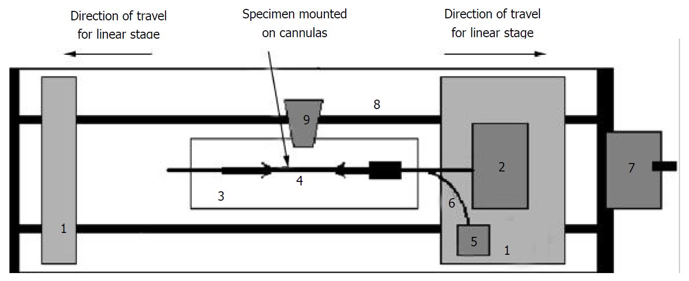
Figure 1 Legend, biaxial test machine setup.
1: Stage, 2: Force transducer, 3: Organ bath, 4: Specimen, 5: Pressure transducer, 6: Infusion channel, 7: Motor for linear stage, 8: Rails for linear stage, 9: Video camera.
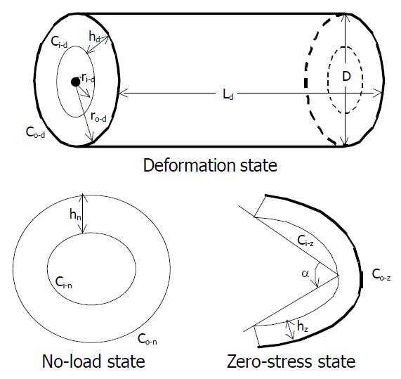
Figure 2 Legend, illustrations of intestinal small intestinal seg-ment in the no-load, zero-stress and deformed states.
C, h, α, denoted the circumference, thickness, and opening angle, respectively. The subscripts n, z, d denoted the no-load state, zero stress state and deformed state, respectively. The sub-scripts i, o referred to the inner (mucosal) surface, outer (serosal) surface, respectively.
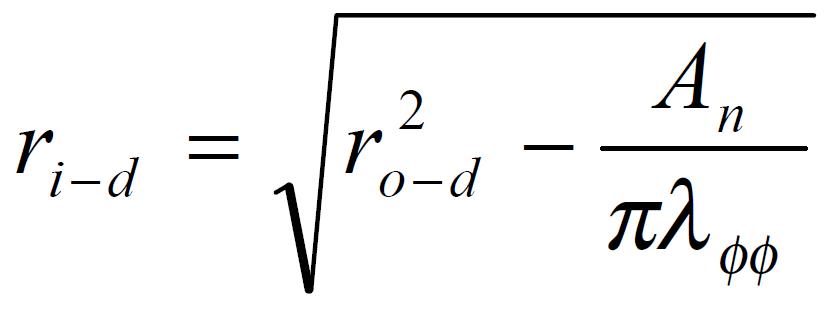
Math 1 Math(A1).
Math 2 Math(A1).
Math 3 Math(A1).
Math 4 Math(A1).
Math 5 Math(A1).
Math 6 Math(A1).
Math 7 Math(A1).
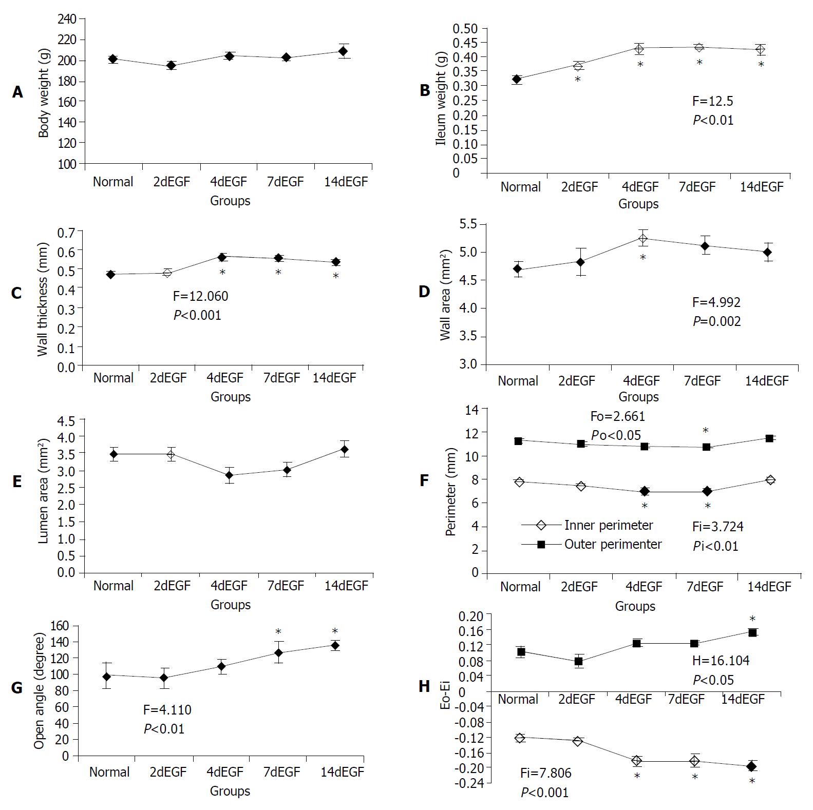
Figure 3 Legend, morphometric data of ileum in the no-load (A-F) and zero-stress states (G-H).
F and P values were from one-way ANOVA for different treatment groups: If significant difference (P < 0.05) was found using one-way ANOVA (marked with a), multiple comparisons with normal controls were done using Dunnet’s test. Significantly different groups were marked with b.
Figure 4 Legend, intestinal stress-strain curves in the EGF-treated and normal control groups.
Translation of the stress-strain curve to the right in the coordinate system implied tissue softening (decreased stiffness) and vice versa.
- Citation: Yang J, Zhao JB, Zeng YJ, Gregersen H. Biomechanical properties of ileum after systemic treatment with epithelial growth factor. World J Gastroenterol 2003; 9(10): 2278-2283
- URL: https://www.wjgnet.com/1007-9327/full/v9/i10/2278.htm
- DOI: https://dx.doi.org/10.3748/wjg.v9.i10.2278


