Copyright
©The Author(s) 2017.
World J Gastroenterol. Dec 7, 2017; 23(45): 8035-8043
Published online Dec 7, 2017. doi: 10.3748/wjg.v23.i45.8035
Published online Dec 7, 2017. doi: 10.3748/wjg.v23.i45.8035
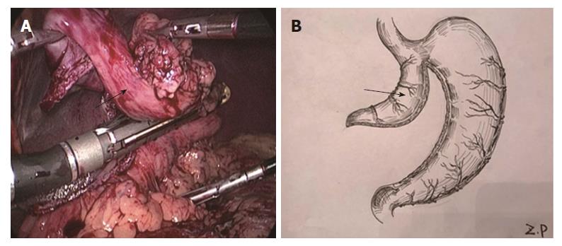
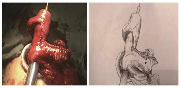
Figure 1 Intraoperative view (A) and schematic diagram (B) of the creation of a gastric pouch (arrows).
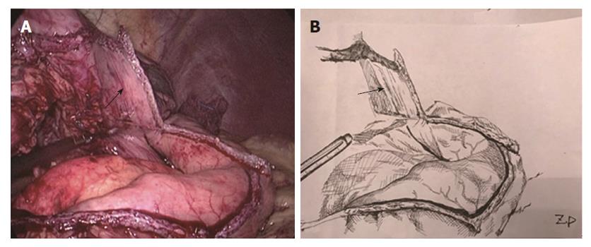
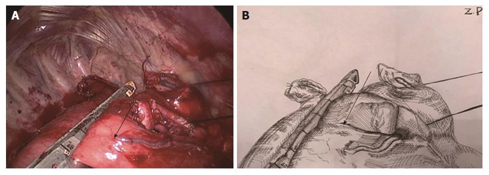
Figure 2 Intraoperative view (A) and schematic diagram (B) of the creation of a gastric tube (arrows indicate the gastric pouch).
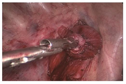
Figure 3 The purse-string suture was tightened and tied to fix the anvil.
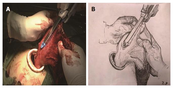
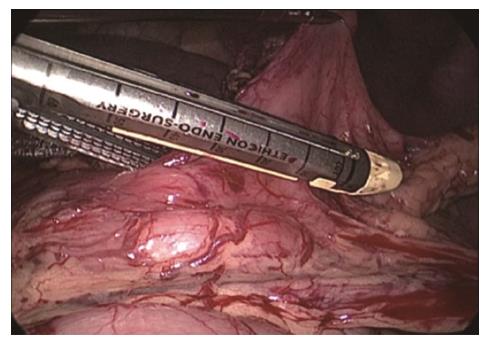
Figure 4 Intraoperative view (A) and schematic diagram (B) of the creation of a gastric tube via the main operating port.
Figure 5 Intraoperative view (A) and schematic diagram (B) of the placement of an anastomat via the gastric pouch and its course through the fundus of the gastric tube (arrows indicate the gastric pouch).
Figure 6 Intraoperative view (A) and schematic diagram (B) of the resection of the connection region (arrows indicate the gastric pouch).
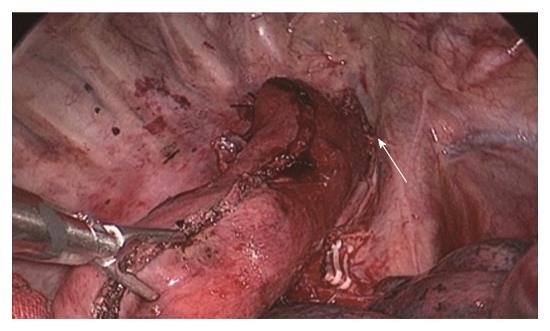
Figure 7 Anastomotic site and gastric tube after anastomosis.
The arrow indicates the anastomotic site.
Figure 8 Stapling angle and length of the first firing.
- Citation: Liu Y, Li JJ, Zu P, Liu HX, Yu ZW, Ren Y. Two-step method for creating a gastric tube during laparoscopic-thoracoscopic Ivor-Lewis esophagectomy. World J Gastroenterol 2017; 23(45): 8035-8043
- URL: https://www.wjgnet.com/1007-9327/full/v23/i45/8035.htm
- DOI: https://dx.doi.org/10.3748/wjg.v23.i45.8035


