Copyright
©The Author(s) 2016.
World J Gastroenterol. Feb 21, 2016; 22(7): 2326-2335
Published online Feb 21, 2016. doi: 10.3748/wjg.v22.i7.2326
Published online Feb 21, 2016. doi: 10.3748/wjg.v22.i7.2326
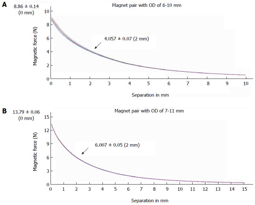
Figure 1 Magnetic force displacement curve.
The magnetic force measured by a universal tensile testing machine is shown as a function of intermagnet separation (in mm) for 2 types of magnet pairs used for choledochojejunostomy magnamosis; 5 samples were tested for each magnet. A: Magnet pair with an outside diameter of 6 mm (biliary part) to 10 mm (enteric part); B: Magnet pair with an outside diameter of 7 mm (biliary part) to 11 mm (enteric part). OD: Outside diameter.
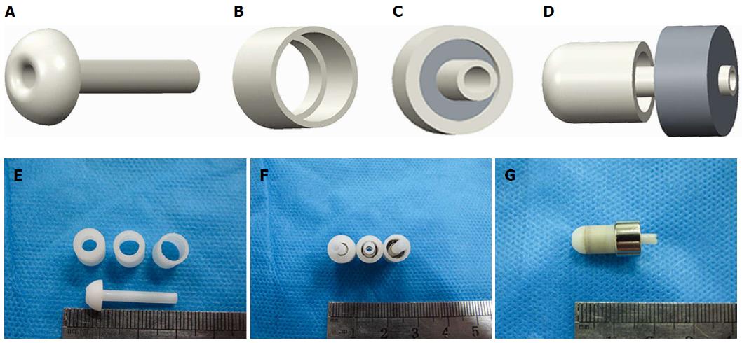
Figure 2 Mode pattern and real pictures of magnet devices.
A: Lateral view of an internal drainage tube; B: View of the biliary part magnet shell; C: Antapical view of the combined biliary part; D: Lateral view of biliary part approach to enteric part; E: The internal drainage tube and shells of different crimping areas; F: Magnets with different pressures; G: Biliary part and enteric part coupled together.
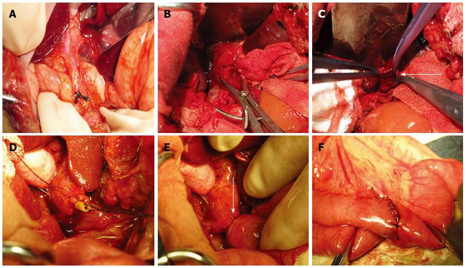
Figure 3 Surgical procedure.
Images illustrating the surgical procedure with a magnet pair. A: The ligation of the distal end of common bile duct near the duodenum. B: Obvious dilatation of the common bile duct can be observed 10 d after ligation; C: Opened common bile duct before placing the biliary part magnet (arrow); D: The biliary part magnet was fixed to the stump of the common bile duct by a purse string; E: The choledochojejunostomy was constructed with the magnet pair (arrow); F: Suture enteroenteric anastomosis between the proximal end of the jejunum and the distal 50 cm of the Roux-en-Y limb.
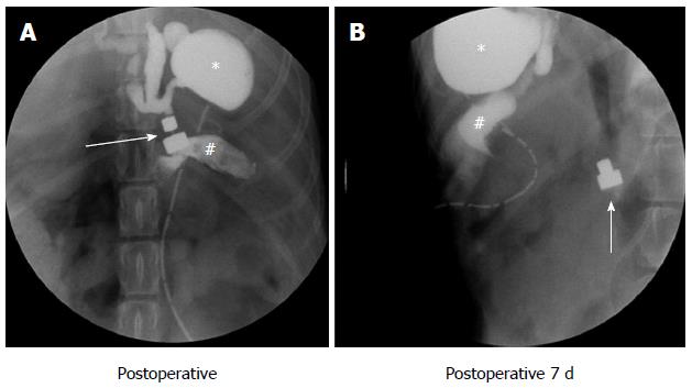
Figure 4 Postoperative abdominal X-ray.
The path of the magnet pairs was monitored via an abdominal X-ray examination. The arrows indicates the magnetic pair, the asterisk indicates the gallbladder and the pound sign indicates the jejunum. A: Abdominal X-ray examination immediately after surgery; the two parts of the magnet pair coupled very well, exhibited good patency and were leak free; B: Daily abdominal radiography until the magnets were shed from the anastomosis.
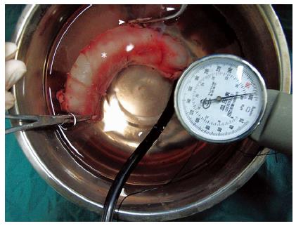
Figure 5 Bursting pressure test.
Mechanical interrogation of anastomotic integrity. The arrowhead indicates the common bile duct, and the asterisk indicates the jejunum. The pointer on the sphygmomanometer is almost at the maximum, but bubbles were not observed.
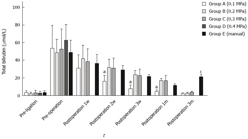
Figure 6 Serum total bilirubin between each group at different time points.
Group A exhibited a faster decrease 2 wk, 3 wk and 1 mo after surgery (ANOVA, aP < 0.05); group E exhibited a significant increase within 3 mo (ANOVA, cP < 0.05); data were not obtained from group D due to a high mortality rate.
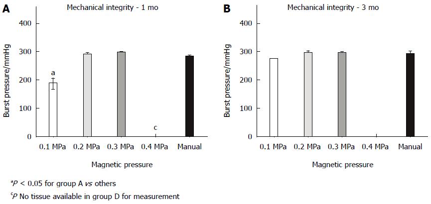
Figure 7 Anastomosis mechanical integrity at 1 (A) and 3 mo (B).
The burst pressure at 1 mo was significantly lower in group A than in other groups (ANOVA, P < 0.05). The burst pressure did not differ between groups at 3 mo (ANOVA, P = 0.052).
- Citation: Xue F, Guo HC, Li JP, Lu JW, Wang HH, Ma F, Liu YX, Lv Y. Choledochojejunostomy with an innovative magnetic compressive anastomosis: How to determine optimal pressure? World J Gastroenterol 2016; 22(7): 2326-2335
- URL: https://www.wjgnet.com/1007-9327/full/v22/i7/2326.htm
- DOI: https://dx.doi.org/10.3748/wjg.v22.i7.2326


