Copyright
©The Author(s) 2015.
World J Gastroenterol. Sep 14, 2015; 21(34): 9982-9992
Published online Sep 14, 2015. doi: 10.3748/wjg.v21.i34.9982
Published online Sep 14, 2015. doi: 10.3748/wjg.v21.i34.9982
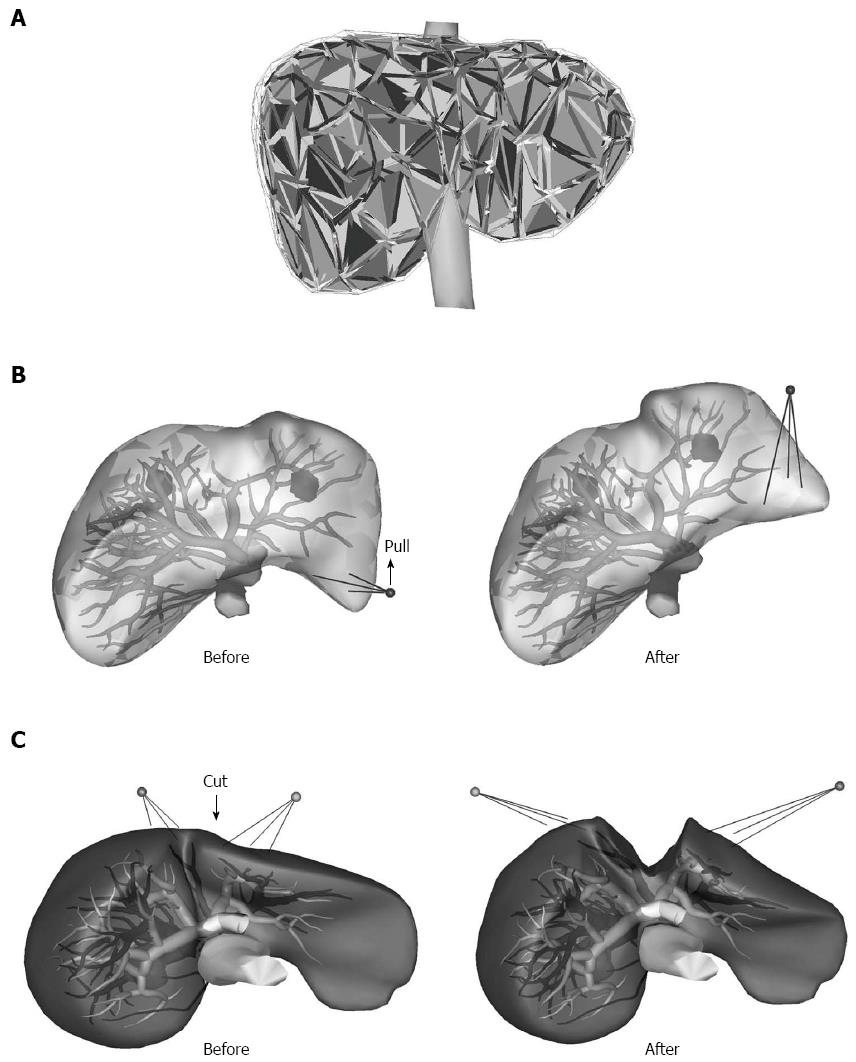
Figure 1 Three-dimensional tetrahedral meshed model of a liver.
A: The liver, inferior vena cava, tumor and gallbladder models were converted into tetrahedral meshed models and considered in the calculation of the physical simulation via the finite element method; B, C: The vessel surface models were placed inside the liver model, and their positions changed according to the deformation of the liver model.
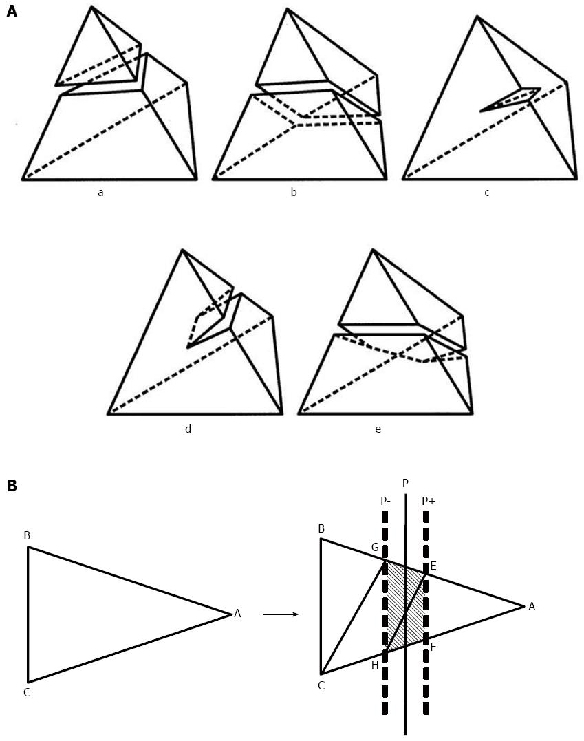
Figure 2 Incision function.
A: The incision function of the liver parenchyma. Incision functions are implemented at the top of the Sofa framework. This function is used for cutting the tetrahedral meshes used in the incisions of the liver parenchyma. The patterns used for cutting the tetrahedral meshes were divided into five types; B: A typical example of triangle subdivision. The triangle ABC above is subdivided by two sheets of cut planes, P+ and P-, into five triangles: AEF, EFH, EHG, GHC, and GCB, as below. Planes P+ and P- are defined by the slightly translating plane P, which cuts the tetrahedrons. Each of the triangles plays a different role. The three triangles between P+ and P- are exposed on the outside of the liver during simulation, whereas the other two are placed inside. Liversim allows the user to delete the exposed triangles to simulate the process of removing the exposed vessels in the cut surface of the liver. Using these functions, a user can cut open the liver parenchyma and remove the exposed segments of the hepatic vessels.
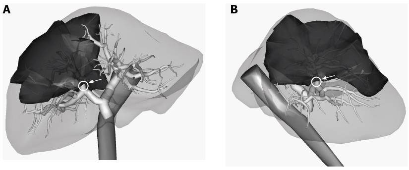
Figure 3 Territory of the anterior portal vein branch is described as deep color territory.
The vascular territory is constructed from a Voronoi tessellation applied to the paths of the intrahepatic vessels. A: Three-dimensional image view from the front of the patient; B: Three-dimensional image view from the patient's right side.
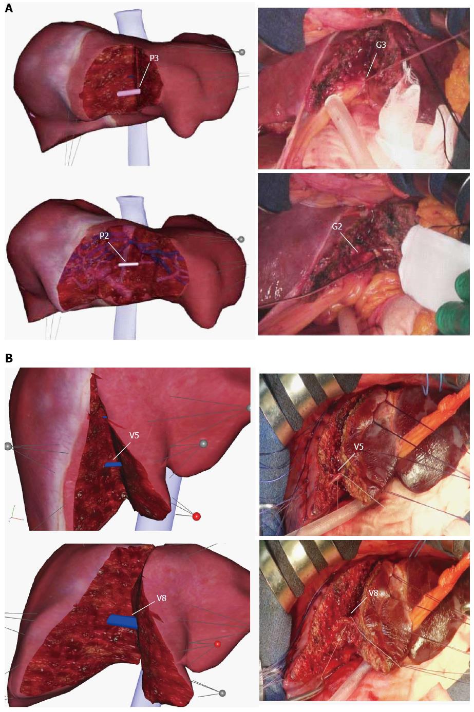
Figure 4 Pictures for comparisons between a virtual hepatectomy and an actual hepatectomy.
The positional relationship of the exposed portal veins and the hepatic veins on the raw surface of the liver is consistent with the virtual hepatectomy using Liversim. A: Case 1, a lateral sectionectomy, is displayed. There was no obvious discrepancy (e.g., in the emergence of P3 (G3) and P2 (G2) or the depth and direction of the resection line) during the resection process between our simulation and the actual surgery; B: Case 2 underwent an extended left hepatectomy, as shown. A good resemblance can be observed between the positional relationship of the exposed V5 and V8 shown in the 3D simulation and observed during the actual hepatectomy. P3: The segment 3 portal branch; P2: The segment 2 portal branch; G3: The segment 3 glissonean pedicle; G2: The segment 2 glissonean pedicle; V5: The hepatic venous branches that drain segment 5; V8: The hepatic venous branches that drain segment 8.
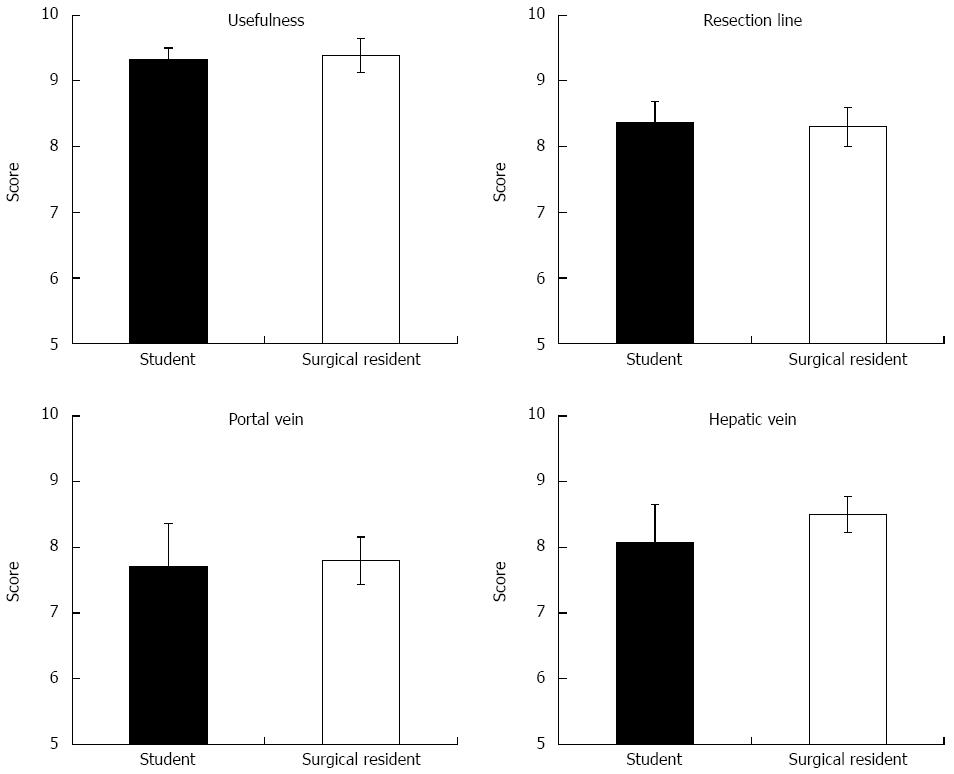
Figure 5 Utility of Liversim, a novel preoperative 3-dimensional liver surgery simulation software program, was assessed using a questionnaire.
In particular, the conformity between the Liversim images and actual surgical observations was evaluated.
- Citation: Oshiro Y, Yano H, Mitani J, Kim S, Kim J, Fukunaga K, Ohkohchi N. Novel 3-dimensional virtual hepatectomy simulation combined with real-time deformation. World J Gastroenterol 2015; 21(34): 9982-9992
- URL: https://www.wjgnet.com/1007-9327/full/v21/i34/9982.htm
- DOI: https://dx.doi.org/10.3748/wjg.v21.i34.9982


