Copyright
©2013 Baishideng Publishing Group Co.
World J Gastroenterol. Sep 28, 2013; 19(36): 6110-6113
Published online Sep 28, 2013. doi: 10.3748/wjg.v19.i36.6110
Published online Sep 28, 2013. doi: 10.3748/wjg.v19.i36.6110
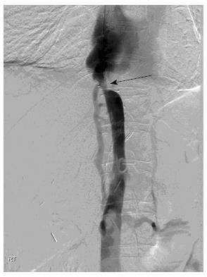
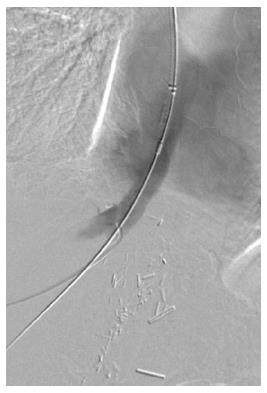
Figure 1 Digital subtraction venogram via a pigtail catheter placed in the infrahepatic inferior vena cava demonstrating inferior vena cava stenosis (arrow) and no reflux of contrast into the transplant hepatic veins.
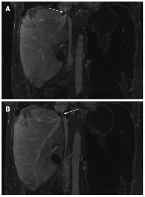
Figure 2 Five-minute steady state imaging.
A: Coronal T1 weighted ultrafast gradient echo steady state magnetic resonance imaging image obtained 5 min following administration of Gadofosveset trisodium demonstrates inferior vena cava stenosis (white arrow); B: Coronal T1 weighted ultrafast gradient echo steady state magnetic resonance imaging image obtained 5 min following administration of gadofosveset trisodium demonstrating patent, but stenosed transplant hepatic vein (white arrow).
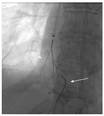
Figure 3 Fluoroscopic image demonstrating a loop snare inserted through the internal jugular vein access (arrowhead), and an angled catheter (arrow) through the right hepatic vein.
Access to the right hepatic vein was achieved via percutaneous ultrasound guided puncture.
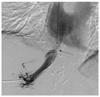
Figure 4 Digital subtraction venogram demonstrating through and through access across the hepatic venous stenosis (arrow).
Figure 5 Completion venoplasty demonstrating satisfactory post venoplasty appearances of the hepatic vein.
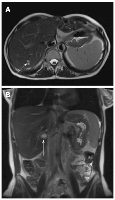
Figure 6 Follow up magnetic resonance imaging axial (A) and coronal (B) balanced gradient echo sequences (True FISP; Siemens Medical, Erlangen, Germany) through the liver performed as part of routine annual tumor surveillance at 1 year following venoplasty of the hepatic vein and inferior vena cava stenosis demonstrated normal appearance of the liver apart from simple parenchymal cysts (arrow).
No ascites was seen.
- Citation: Strovski E, Liu D, Scudamore C, Ho S, Yoshida E, Klass D. Magnetic resonance venography and liver transplant complications. World J Gastroenterol 2013; 19(36): 6110-6113
- URL: https://www.wjgnet.com/1007-9327/full/v19/i36/6110.htm
- DOI: https://dx.doi.org/10.3748/wjg.v19.i36.6110


