Copyright
©The Author(s) 2016.
World J Radiol. Jun 28, 2016; 8(6): 537-555
Published online Jun 28, 2016. doi: 10.4329/wjr.v8.i6.537
Published online Jun 28, 2016. doi: 10.4329/wjr.v8.i6.537
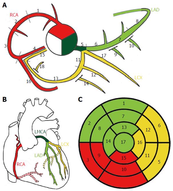
Figure 3 Schematic representation of normal coronary anatomy[11].
A: Coronary segments scheme proposed in SCCT guidelines for the interpretation and reporting of coronary computed tomography and used by Society of Cardiovascular Computer Tomography; B: Schematic representation of the coronary arteries. C: Circumferential polar plot of the 17 myocardial segments[56] with corresponding coronary artery territories. A-1, 2 and 3: Proximal, mid and distal RCA; 4: Right posterior descending artery; 5: Left main coronary artery; 6, 7 and 8: Proximal, mid and distal LAD; 9 and 10: First and second diagonal branches; 11: Proximal LCX; 12: First obtuse marginal branch; 13: Mid and distal LCX; 14: Second marginal branch; 15: Left posterior descending artery; 16: Right posterior-lateral branch; 17: Ramus intermedius; 18: Left posterior-lateral branch. RCA: Right coronary artery; LMCA: Left main coronary artery; LAD: Left anterior descending; LCX: Left circumflex artery.
- Citation: Villa AD, Sammut E, Nair A, Rajani R, Bonamini R, Chiribiri A. Coronary artery anomalies overview: The normal and the abnormal. World J Radiol 2016; 8(6): 537-555
- URL: https://www.wjgnet.com/1949-8470/full/v8/i6/537.htm
- DOI: https://dx.doi.org/10.4329/wjr.v8.i6.537


