Copyright
©The Author(s) 2015.
World J Cardiol. Sep 26, 2015; 7(9): 562-570
Published online Sep 26, 2015. doi: 10.4330/wjc.v7.i9.562
Published online Sep 26, 2015. doi: 10.4330/wjc.v7.i9.562
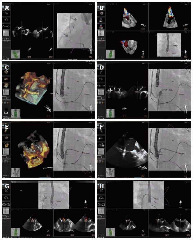
Figure 2 EchoNavigator® during MitraClip® procedures.
A demonstrates the Echo-view on the left, depicting an X-plane-view of the interatrial septum. The interventionalist can set markers in this view for exact delineation of the optimal puncture site that will automatically appear in the X-ray-view on the right. A 3D full volume color doppler image is shown in the right upper panel of B. After cropping into this data set, the maximum regurgitant jet was depicted and marked within this image. On the left side of C, a 3D view of the septum with the delivery system and especially the three points of interest (Septum, Crista, and Mitral valve) is demonstrated. The connection between these three points creates a virtual triangle in the X-ray-view on the right side of C, outlining the area at risk outside this triangle in the X-ray-view in D, where contact of the MitraClip® device with its surrounding structures potentially can lead to complications, such as perforation with cardiac tamponade. E demonstrate the process of Clip orientation orthogonally towards the commissure in the 3D view, and the grasping of leaflets in the 2D intercommisural view in F. The X-ray-view in both figures on the right display demonstrates the correct position of the Clip right on top of the red marker, corresponding with the echo images. G demonstrates the residual regurgitant jet on the lateral side of the first Clip. This jet was marked in the echo image and was then used for orientating a second Clip in the X-Ray image, as demonstrated in H. 2D: Two-dimensional; 3D: Three-dimensional.
- Citation: Balzer J, Zeus T, Hellhammer K, Veulemans V, Eschenhagen S, Kehmeier E, Meyer C, Rassaf T, Kelm M. Initial clinical experience using the EchoNavigator®-system during structural heart disease interventions. World J Cardiol 2015; 7(9): 562-570
- URL: https://www.wjgnet.com/1949-8462/full/v7/i9/562.htm
- DOI: https://dx.doi.org/10.4330/wjc.v7.i9.562


