Copyright
©The Author(s) 2018.
World J Cardiol. Sep 26, 2018; 10(9): 119-122
Published online Sep 26, 2018. doi: 10.4330/wjc.v10.i9.119
Published online Sep 26, 2018. doi: 10.4330/wjc.v10.i9.119
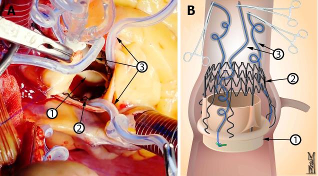
Figure 2 Intraoperative picture.
A: Graphic presentation of the prosthesis after deployment; B: Prosthesis. Notice that the snare should not lie between the ring of the prosthesis and the annulus of the aorta. 1 represents valve prosthesis; 2 represents valve stent; 3 represents the snares.
- Citation: Mashhour A, Zhigalov K, Szczechowicz M, Mkalaluh S, Easo J, Eichstaedt H, Borodin D, Ennker J, Weymann A. Snugger method - The Oldenburg modification of perceval implantation technique. World J Cardiol 2018; 10(9): 119-122
- URL: https://www.wjgnet.com/1949-8462/full/v10/i9/119.htm
- DOI: https://dx.doi.org/10.4330/wjc.v10.i9.119


