Copyright
©The Author(s) 2025.
World J Gastroenterol. Apr 14, 2025; 31(14): 103921
Published online Apr 14, 2025. doi: 10.3748/wjg.v31.i14.103921
Published online Apr 14, 2025. doi: 10.3748/wjg.v31.i14.103921
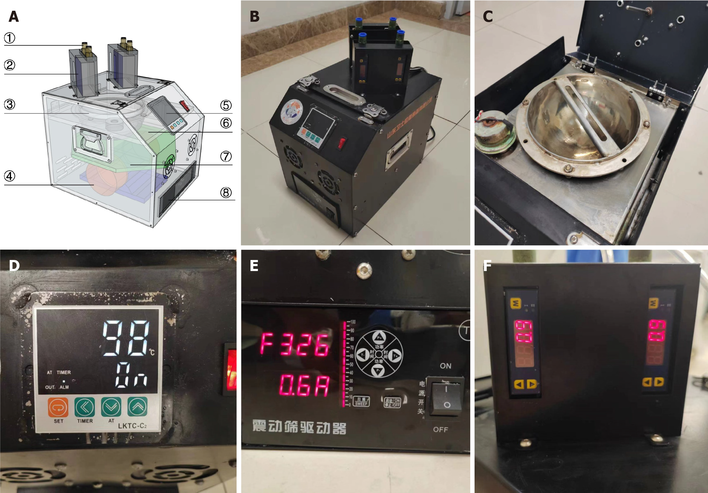
Figure 1 Schematic and photos of the vaporized hydrogen peroxide generation device.
A: The perspective view of the experimental device; B: The actual view of the experimental device; C: Reaction vessel; D: Temperature control panel; E: Ultrasonic control panel; F: Flow meter. 1Gas nozzle; 2Flow meter; 3Reaction vessel; 4Ultrasonic generator; 5Temperature control panel; 6Heating plate; 7Vibration plate; 8Ultrasonic control panel.
- Citation: Zhao C, Qi LH, Li LS, Wang YY, Liang T, Chai NL. Using vaporized hydrogen peroxide for anhydrous disinfection of gastrointestinal endoscopes. World J Gastroenterol 2025; 31(14): 103921
- URL: https://www.wjgnet.com/1007-9327/full/v31/i14/103921.htm
- DOI: https://dx.doi.org/10.3748/wjg.v31.i14.103921


