Copyright
©2011 Baishideng Publishing Group Co.
World J Clin Oncol. Apr 10, 2011; 2(4): 179-186
Published online Apr 10, 2011. doi: 10.5306/wjco.v2.i4.179
Published online Apr 10, 2011. doi: 10.5306/wjco.v2.i4.179
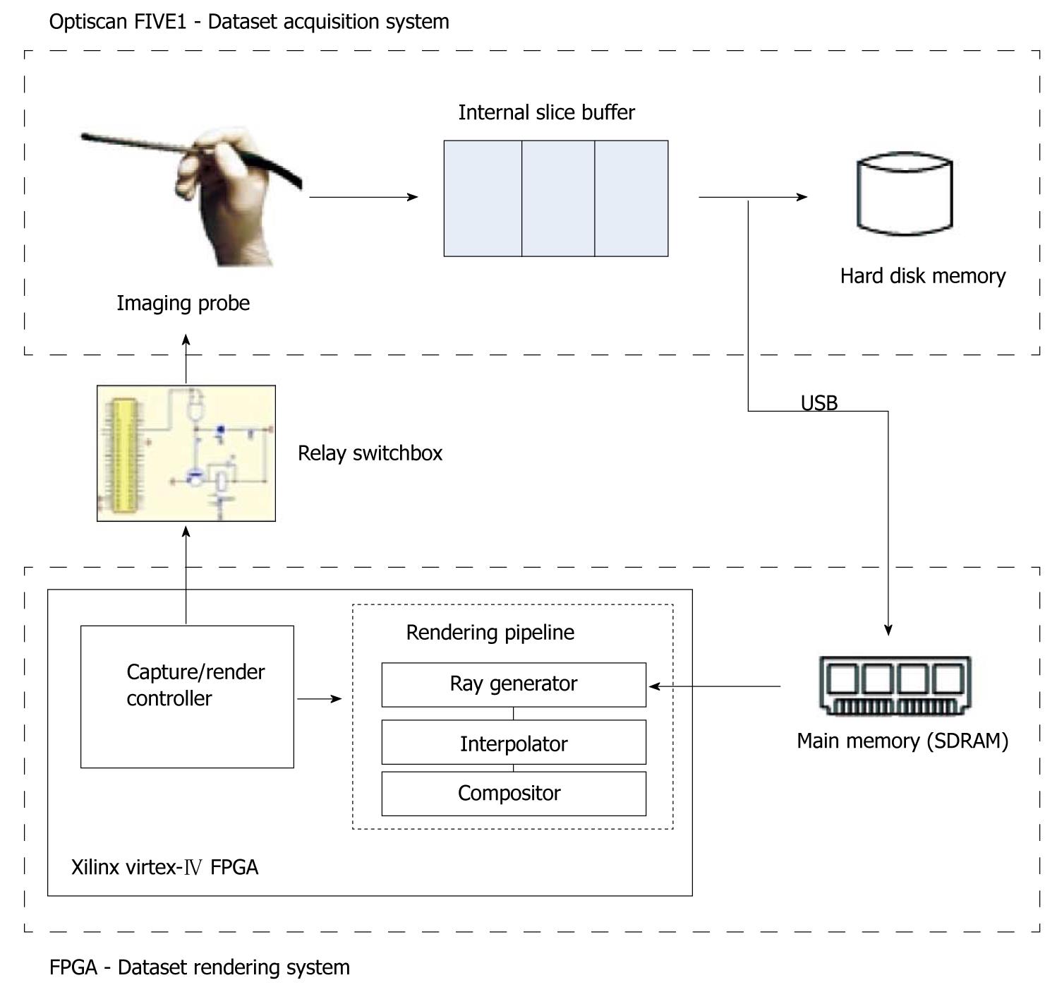
Figure 1 The system architecture.
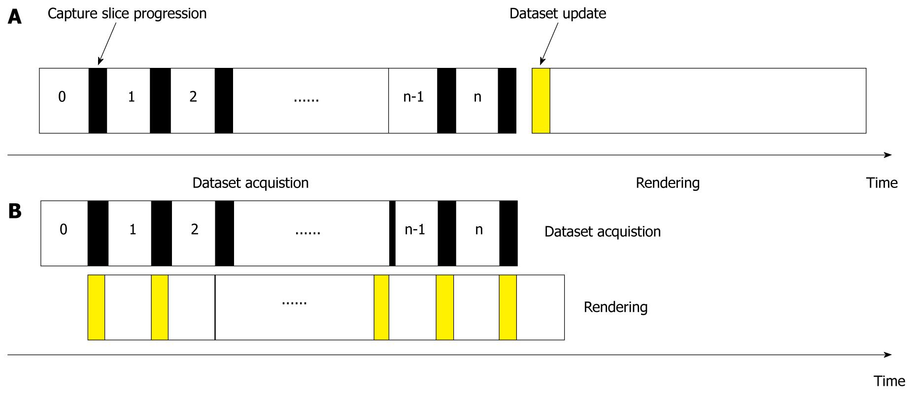
Figure 2 Imaging-rendering allocation.
A: Conventional procedure; B: Simultaneous dataset capture and rendering.
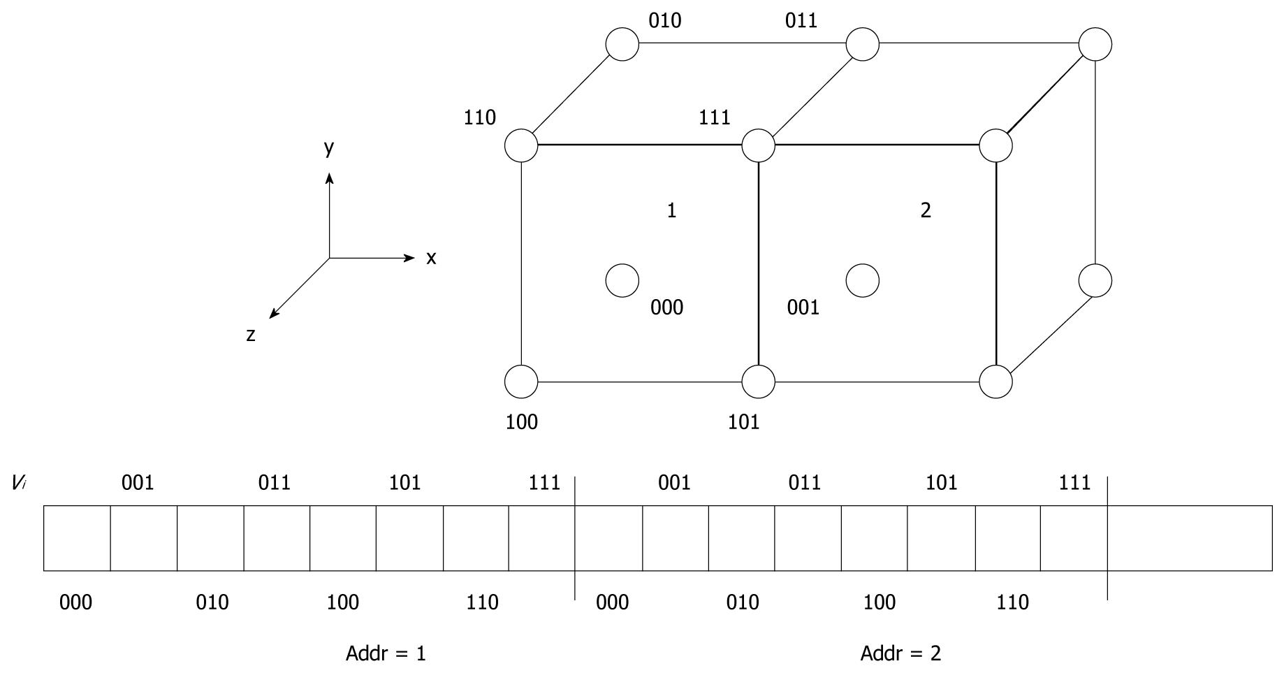
Figure 3 Cubic memory organization: Voxels are arranged in memory as cubes.
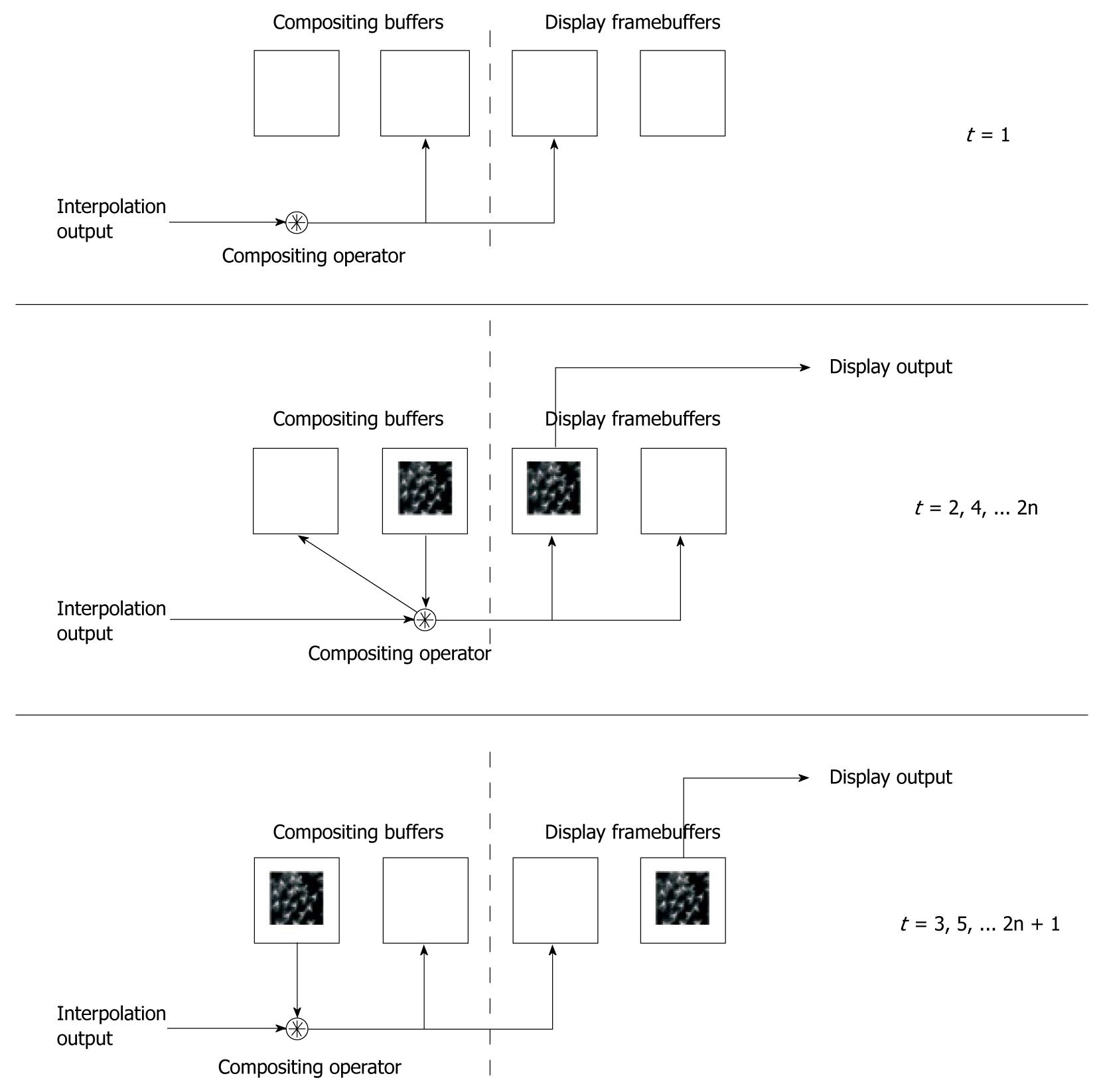
Figure 4 Framebuffers for accumulative rendering mode.
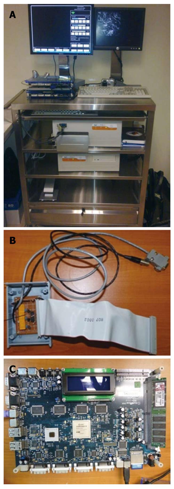
Figure 5 The Laser scanning confocal endomicroscope imaging-rendering prototype system.
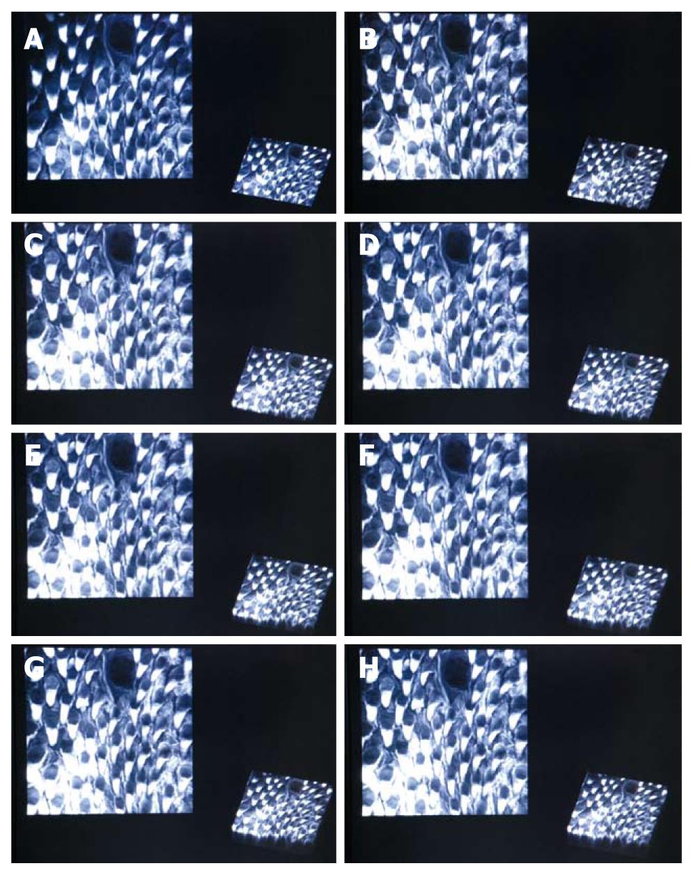
Figure 6 Online rendering of the mouse tongue surface across increasing number of slices.
A: 2 slices; B: 10 slices; C: 15 slices; D: 20 slices; E: 25 slices; F: 30 slices; G: 35 slices; H: 38 slices.
- Citation: Chiew WM, Lin F, Qian K, Seah HS. Online volume rendering of incrementally accumulated LSCEM images for superficial oral cancer detection. World J Clin Oncol 2011; 2(4): 179-186
- URL: https://www.wjgnet.com/2218-4333/full/v2/i4/179.htm
- DOI: https://dx.doi.org/10.5306/wjco.v2.i4.179


