Copyright
©The Author(s) 2016.
World J Cardiol. Apr 26, 2016; 8(4): 323-326
Published online Apr 26, 2016. doi: 10.4330/wjc.v8.i4.323
Published online Apr 26, 2016. doi: 10.4330/wjc.v8.i4.323
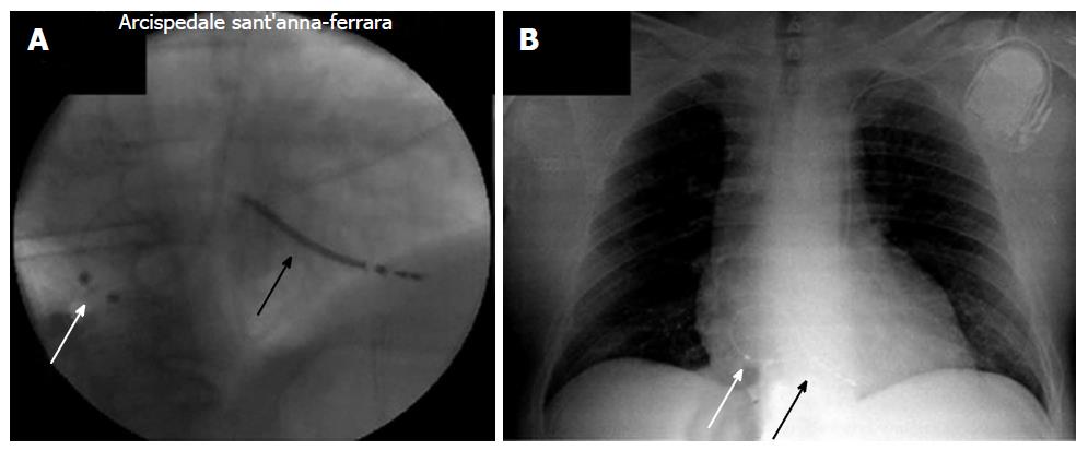
Figure 1 Final position of implantable cardioverter defibrillator sensing dipole.
A: Fluoroscopic posteroanterior view during implantation; B: Chest X-ray after implantation. Note the position of atrial sensing dipole (white arrow) and defibrillation coil (black arrow).
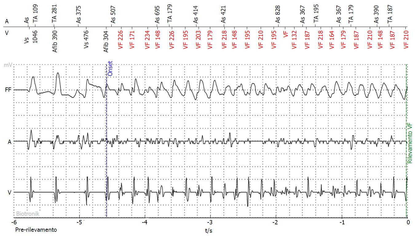
Figure 2 Ventricular fibrillation event.
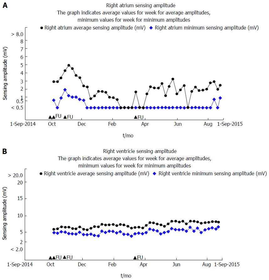
Figure 3 Trends of atrial and ventricular sensing during 10 mo of follow-up.
FU: Follow-up.
- Citation: Malagù M, Toselli T, Bertini M. Single lead catheter of implantable cardioverter-defibrillator with floating atrial sensing dipole implanted via persistent left superior vena cava. World J Cardiol 2016; 8(4): 323-326
- URL: https://www.wjgnet.com/1949-8462/full/v8/i4/323.htm
- DOI: https://dx.doi.org/10.4330/wjc.v8.i4.323


