Copyright
©The Author(s) 2020.
World J Gastroenterol. Jan 28, 2020; 26(4): 383-392
Published online Jan 28, 2020. doi: 10.3748/wjg.v26.i4.383
Published online Jan 28, 2020. doi: 10.3748/wjg.v26.i4.383
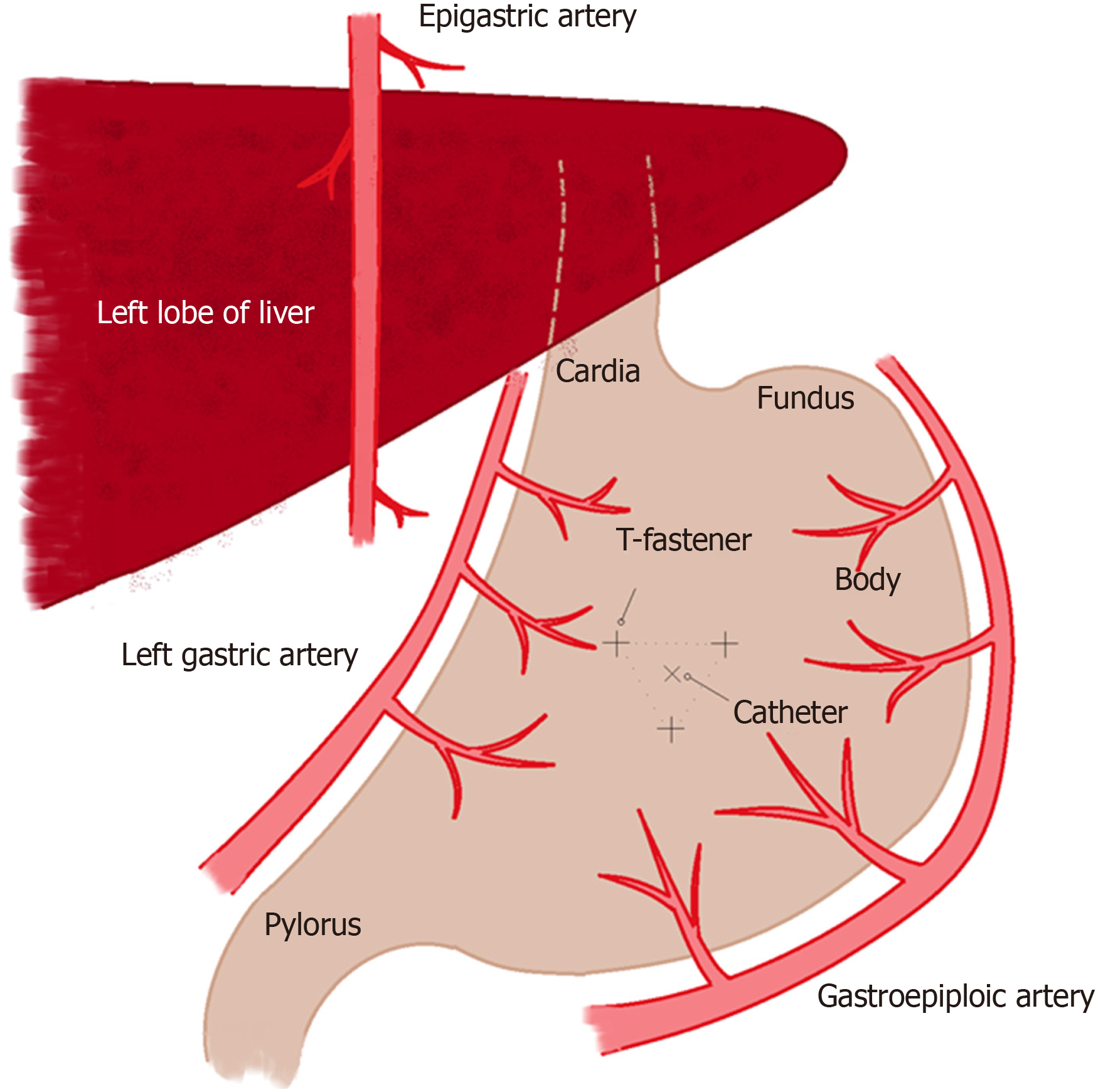
Figure 1 Schematic drawing of procedure planning for T-fasteners and percutaneous endoscopic gastrostomy entry sites.
T-fasteners are positioned triangularly 1 inch away from each other. The ideal position should be half way between the lesser and greater curvatures. Catheter should enter in the center of the triangle and aim towards the pylorus.
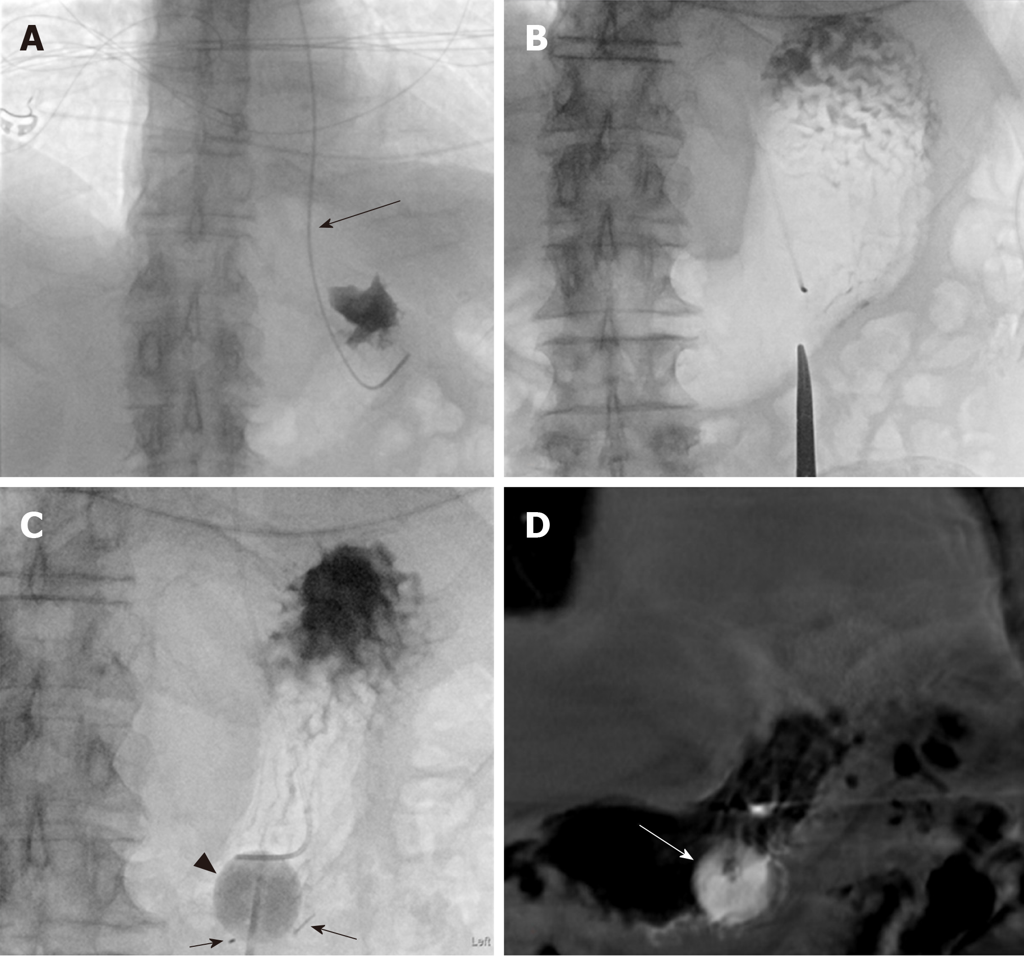
Figure 2 Eighty-one-year-old male with a past medical history of diabetes mellitus, hypertension, perforated diverticulitis status post resection with colostomy and adenocarcinoma of the esophagus status post neoadjuvant chemotherapy.
Patient was admitted for failure to thrive and percutaneous gastrostomy tube placement was requested. An 18-French Entuit gastrostomy tube was placed within a 22-French peel-away sheath. The procedure time was 44 min. Fluoroscopy time was 8 min 6 s and Air Kerma was 280 mGy. This procedure was challenging due to the inability to keep the stomach inflated and glucagon was avoided given the medical history of diabetes mellitus. The gastrostomy tube was started to be used for enteral feeding 24 h after the procedure. A: Advancement of a 5-French MPA catheter (arrow) into the stomach along with a 0.035 Glidewire. The position of the MPA catheter was confirmed with a small amount of iodinated contrast injection; B: Insufflation of the stomach with air though the MPA catheter. A hemostat was used to mark the entry site; C: Placement of the three T-bar fasteners (arrows) as well as the gastrostomy tube with balloon inflated using a mixtures of sterile water with minimal amount of contrast (arrowhead); D: A post-procedural cone-beam computed tomography was performed due to the challenge of keeping the stomach insufflated with air. The cone beam computed tomography showed the gastrostomy tube with the inflated balloon (arrow) in the gastric body. Of note the gastrostomy balloon appears slightly radiopaque due to inflation using a mixture of sterile water with minimal amount of contrast. After completion of the procedure the 5-French MPA catheter was removed.
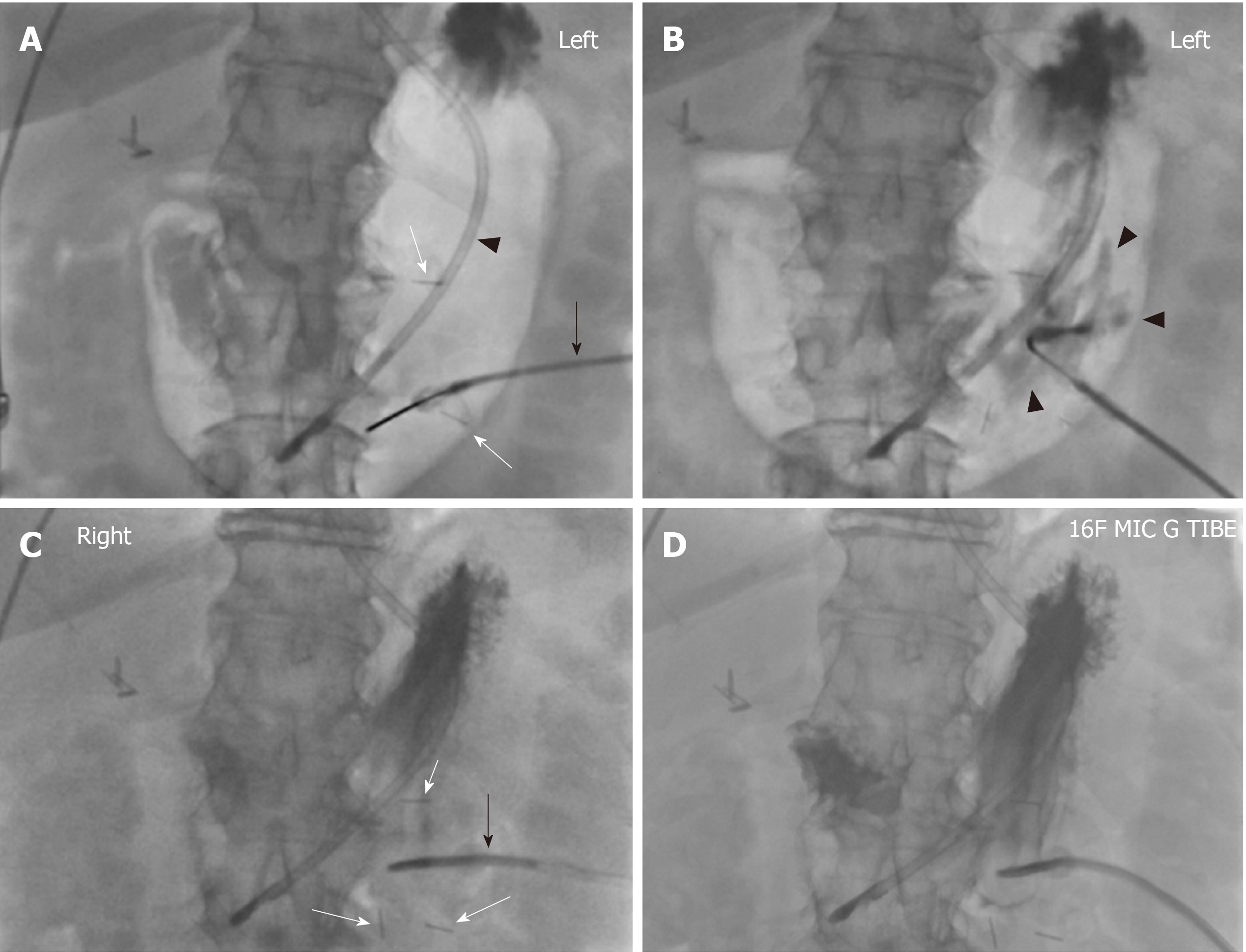
Figure 3 Seventy-six-year-old female with a history of upper extremity edema, intracranial hemorrhage and dysphagia referred for placement of percutaneous gastrostomy tube due to dysphagia with high aspiration risk.
A 16-French gastrostomy tube was placed through a 20-French peel-away sheath. The procedure time was 23 min. Fluoroscopy time was 3 min 24 s and Air Kerma was 43 mGy. No challenge was encountered during the procedure and the gastrostomy tube was started to be used for enteral feeding 24 h after the procedure. A: Dobhoff tube (arrowhead) with its tip in the gastric body was placed before the patient came to the procedure suite. The stomach was manually inflated with air. T-bar fasteners (white arrow) were advanced into the gastric body. Note the connected tubing (black arrow) which contained iodinated contrast; B: Iodinated contrast was injected into the gastric body through the T-bar fastener to confirm intraluminal location. Note the outlines of gastric rugae (black arrowheads); C: The three T-bar fasteners (white arrows) are positioned in a triangular fashion. Note the gastrostomy tube (black arrow) was angulated towards the antrum and pylorus facilitating later conversion to a gastrojejunostomy tube; D: Contrast injection through the gastrostomy tube ascertains the intragastric placement of the tube.
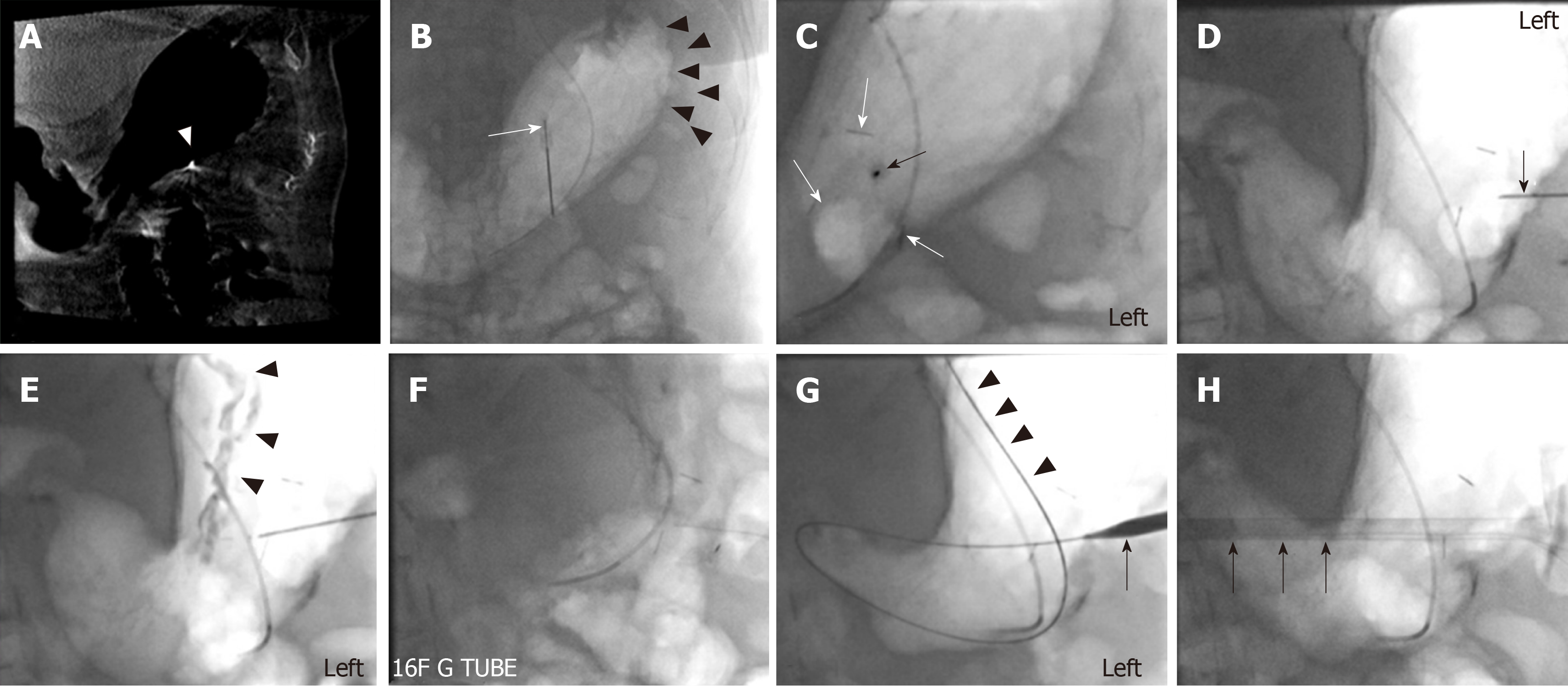
Figure 4 Ninety-four-year-old female with a history of moderately differentiated adenocarcinoma of the esophagus referred for percutaneous gastrostomy tube placement.
A 16-French gastrostomy tube was placed through a 20-French peel-away sheath. Procedure time was 21 min. Fluoroscopy time was 6 min 18 s and Air Kerma was 81.5 mGy. The gastrostomy tube was started to be used for enteral feeding 24 h after the procedure. A: A pre-procedural cone-beam CT was obtained since no CT abdomen was available. A 5-French MPA catheter was placed along with a 0.035 Glidewire. The stomach was manually inflated with air. Arrowhead points to a 21-gauge short local anesthetic needle left in place for entry site planning; B: Placement of the first T-bar fastener (white arrow). Again, note the inflated stomach (arrowheads); C: Note the three T-bar fasteners as linear densities (white arrows). An 18-French needle was visualized at the access site in the left anterior oblique projection lined. The needle (black arrow) was in line with the radiation beam and was aiming towards the antrum and pylorus; D: In the right anterior oblique projection, the depth of the needle (black arrow) can be visualized penetrating the gastric wall; E, F: With iodinated contrast injection, the gastric rugae (arrowheads) could be visualized, thus confirming the intragastric location of the needle; G: The advancement of the 0.035 Amplatz wire (arrowheads) over the needle was pursued. After subsequent tract dilatation the peel-way sheath (arrow) was advanced over the Amplatz; H: The gastrostomy tube (arrow) was advanced through the peel-away sheath. After completion of the procedure the MPA catheter was removed.
- Citation: Partovi S, Li X, Moon E, Thompson D. Image guided percutaneous gastrostomy catheter placement: How we do it safely and efficiently. World J Gastroenterol 2020; 26(4): 383-392
- URL: https://www.wjgnet.com/1007-9327/full/v26/i4/383.htm
- DOI: https://dx.doi.org/10.3748/wjg.v26.i4.383


