Copyright
©The Author(s) 2017.
World J Gastroenterol. May 28, 2017; 23(20): 3684-3689
Published online May 28, 2017. doi: 10.3748/wjg.v23.i20.3684
Published online May 28, 2017. doi: 10.3748/wjg.v23.i20.3684
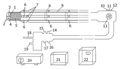
Figure 1 Schematic diagram of negative-pressure suction small intestine endoscope.
1: Observation eyehole; 2: Windows for outgoing light; 3: Clamp tube; 4: Nozzle; 5: Rotating section; 6: Suction tube retainers; 7: Suction hole; 8: Slider retainer; 9: Slider; 10: Button for water and air inlet; 11: Button for water and air suction inlets; 12: Biopsy sample inlet; 13: Button for rotation of external propeller; 14: Air inlet; 15: Water inlet; 16: Air and water suction inlet; 17: Ground wire inlet; 18: Input terminal of heatless light source; 19: Image output terminal; 20: Main engine; 21: Monitor; 22: Air compressor. The length of the negative-pressure suction small intestine endoscope is 2.5 m. The main endoscope diameter is 12 mm. The imaging system used is Medical CMOS. The power system involves negative-pressure suction, and the light used is cold light.
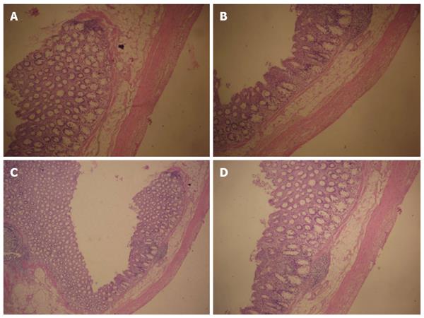
Figure 2 Light microscopic images of a tissue section from an area of the small intestine to which endoscopic negative-pressure suction had been applied in vivo.
A: No damage to the smooth muscle is evident; B: No histologic damage is evident; C: No submucosal or glandular damage is present; D: No submucosal damage is present. Hematoxylin-eosin staining, × 400 magnification.
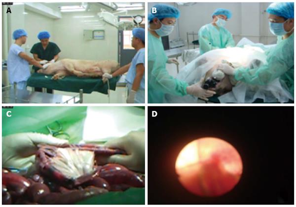
Figure 3 Animal experiments using small intestine endoscope.
A: Animals were fasted for 2 d prior to being anesthetized with ketamine hydrochloride injection (5 mg/kg); B: The endoscope was inserted into the mouth of the pig; C: An attempt was made to reach the ileocecal junction; D: A picture obtained by using the small intestine endoscope.
- Citation: Liu JH, Liu DY, Wang L, Han LP, Qi ZY, Ren HJ, Feng Y, Luan FM, Mi LT, Shan SM. Animal experimental studies using small intestine endoscope. World J Gastroenterol 2017; 23(20): 3684-3689
- URL: https://www.wjgnet.com/1007-9327/full/v23/i20/3684.htm
- DOI: https://dx.doi.org/10.3748/wjg.v23.i20.3684


