Copyright
©The Author(s) 2023.
World J Orthop. Nov 18, 2023; 14(11): 800-812
Published online Nov 18, 2023. doi: 10.5312/wjo.v14.i11.800
Published online Nov 18, 2023. doi: 10.5312/wjo.v14.i11.800
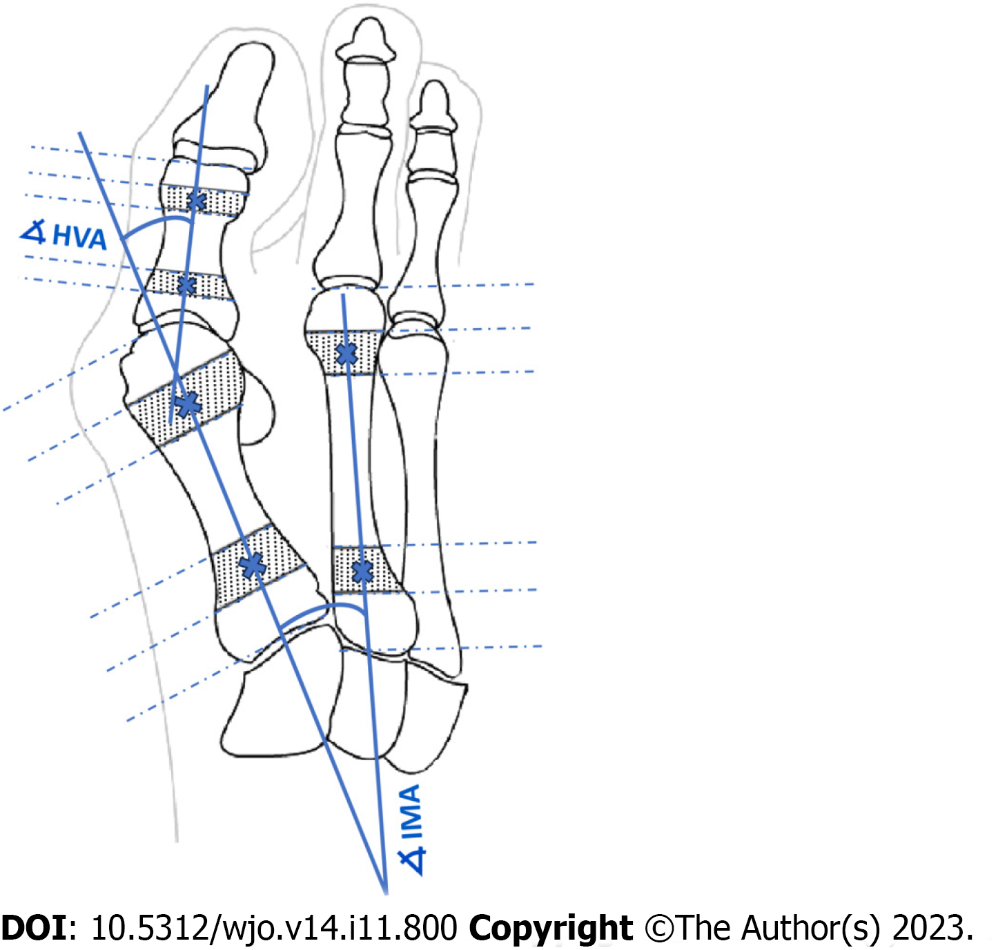
Figure 1 Determination of angles of hallux valgus as described by AOFAS.
HVA: Hallux valgus angle; IMA: Intermetatarsal angle.
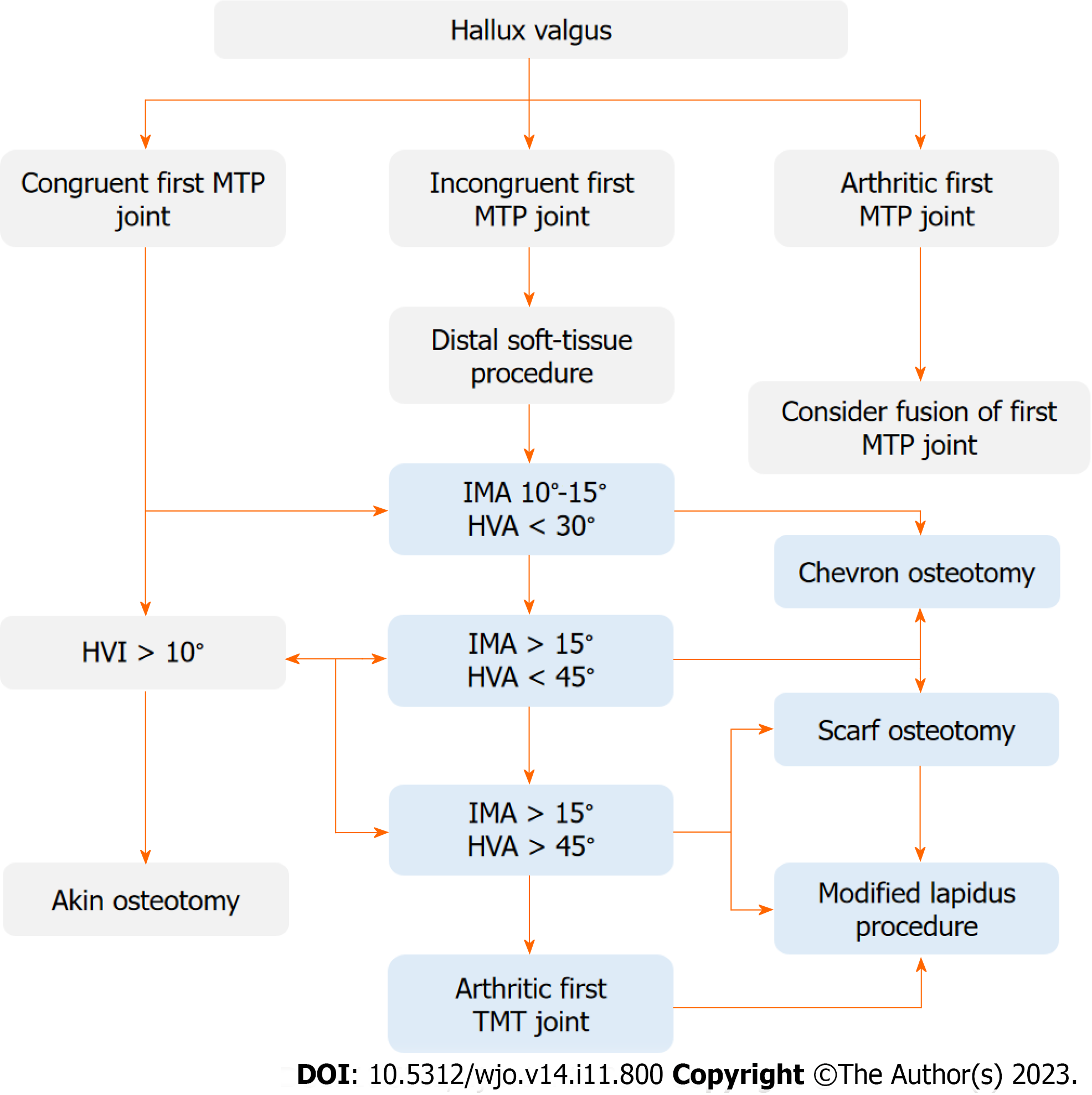
Figure 2 Operative treatment algorithm of hallux valgus.
D1 - decision for intermetatarsal angle (IMA) 10°-15° and hallux valgus angle (HVA) < 30°, D2 - decision for IMA > 15° and HVA < 45°, D3 - decision for IMA > 15° and HVA > 45°. HVA: Hallux valgus angle; HVI: Hallux valgus interphalangeus; IMA: Intermetatarsal angle; MTP: Metatarsophalangeal; TMT: Tarsometatarsal.
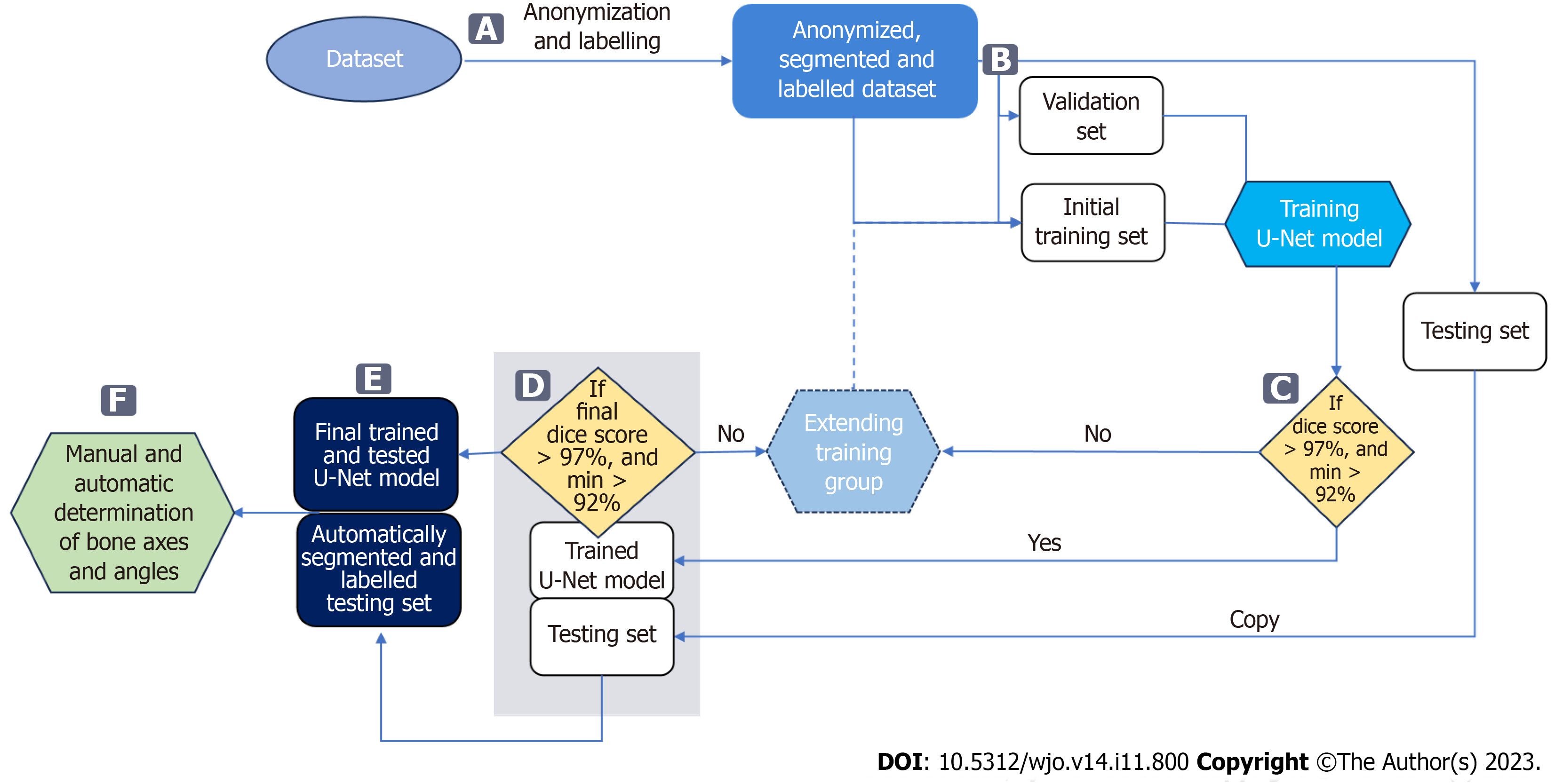
Figure 3 Data flow in the proposed approach.
A: Bones are manually segmented and labelled from anonymized input radiographs to perform multi-class segmentation using a U-Net neural network; B: Radiographs are then randomly assigned to three subsets: training, validation, and testing; C: The accuracy of bone segmentation in each training cycle of the U-Net is validated on a fixed validation subset consisting of 20 radiographs. The U-Net network is trained on a training subset initially consisting of 50 radiographs, which is increased by 10 each training cycle until achieving average Sørensen–Dice index (SDI) > 97% on the validation set; D: Once the network achieves an SDI > 0.97, calculated on the testing subset, the U-Net model completes. If SDI is not > 0.97, the training subset is extended and the U-Net is retrained; E: The final U-Net model is used to segment and label bones on all testing radiographs; F: These are used to automatically determine reference points and measure hallux valgus and intermetatarsal angles.
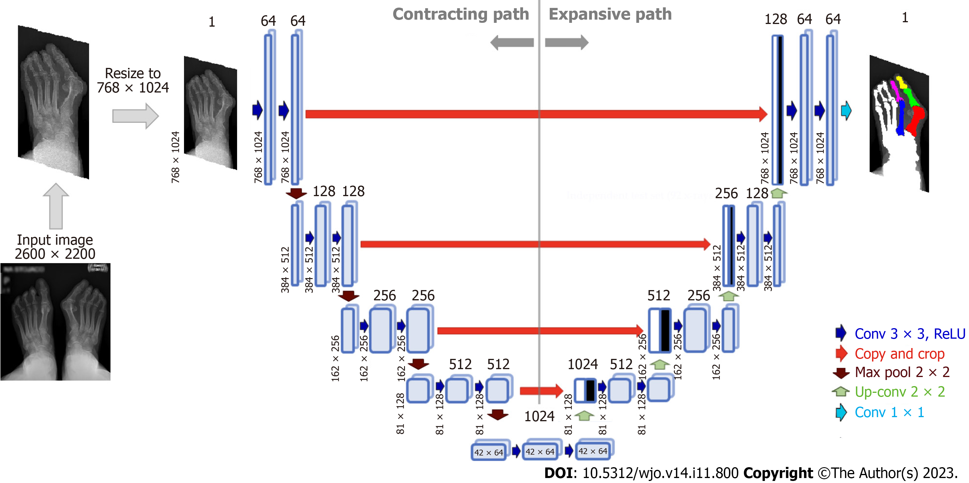
Figure 4 Architecture of U-Net neural network for bone segmentation from radiographs.
The network consists of an encoder (contracting path), which encodes an input image size of 768 × 1024 pixels to 42 × 64 × 1024 feature tensor at the bottleneck, and a decoder (expanding path) that decodes the feature tensor to the segmented image of the same size as the input image. The decoder follows the typical architecture of a convolutional network. Each block in the decoder consists of two 3 × 3 convolutions, each followed by a rectified linear unit (ReLU) and a 2 × 2 max pooling with stride 2 for down-sampling. Each down-sampling step of the encoder doubles the number of feature channels and decreases the image resolution by half. Every block in the decoder comprises upsampling the feature map followed by a 2 × 2 convolution that halves the number of feature channels - a concatenation with the correspondingly cropped feature map from the contracting path - and two 3 × 3 convolutions, each followed by a ReLU.
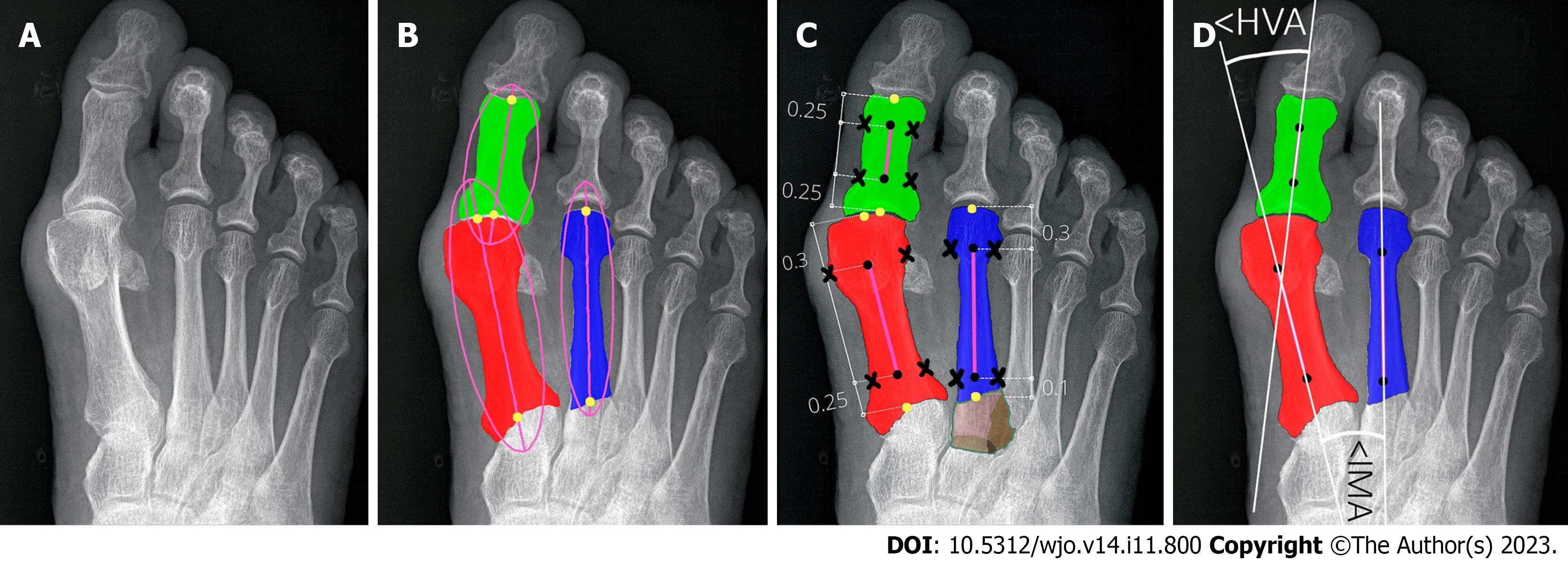
Figure 5 Determining reference points of first and second metatarsals and hallucial proximal phalanx.
A: Input radiograph; B: Three bones of interest: 1,2MT, and hallucial PP were approximated by ellipses to estimate bone axes, which were then used to determine bone endpoints; C: The elliptical axes were split into three parts with specific proportions to determine segment endpoints (marked by black dots) and reference points of the respective bone being established on a transverse line perpendicular to the longitudinal at a point equidistant from the outer border of the medial and lateral cortices (black crosses). Brown color show unsegmented (bone overlap) areas of the proximal epiphyseal of the second metatarsal bone; D: The central axes (white lines) were automatically determined through reference points (marked by black dots).
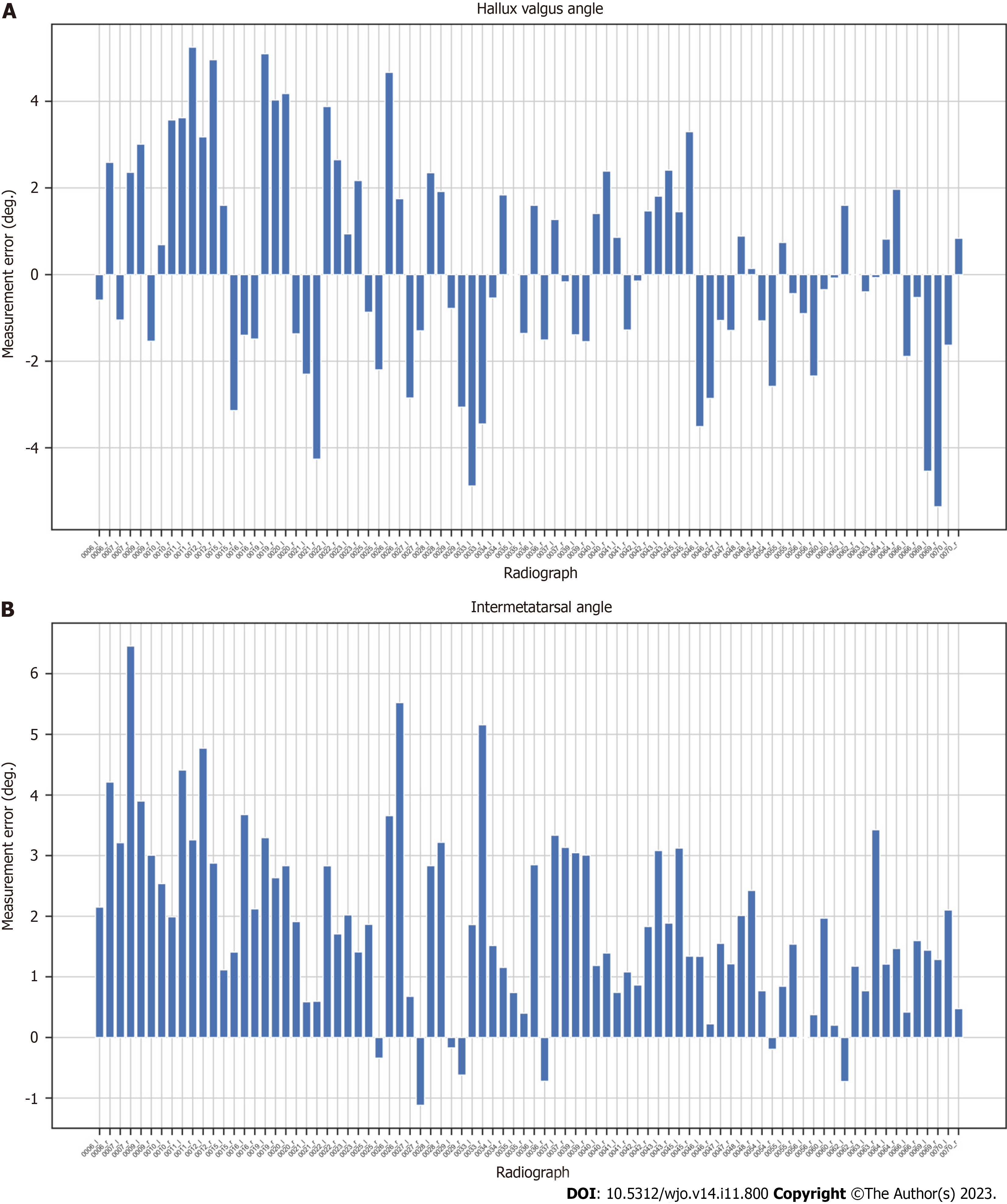
Figure 6 Measurement errors (in degrees) for AI (our algorithm) compared to orthopedic surgeon (OA2) for each radiograph.
A: Hallux valgus angle; B: Intermetatarsal angle.
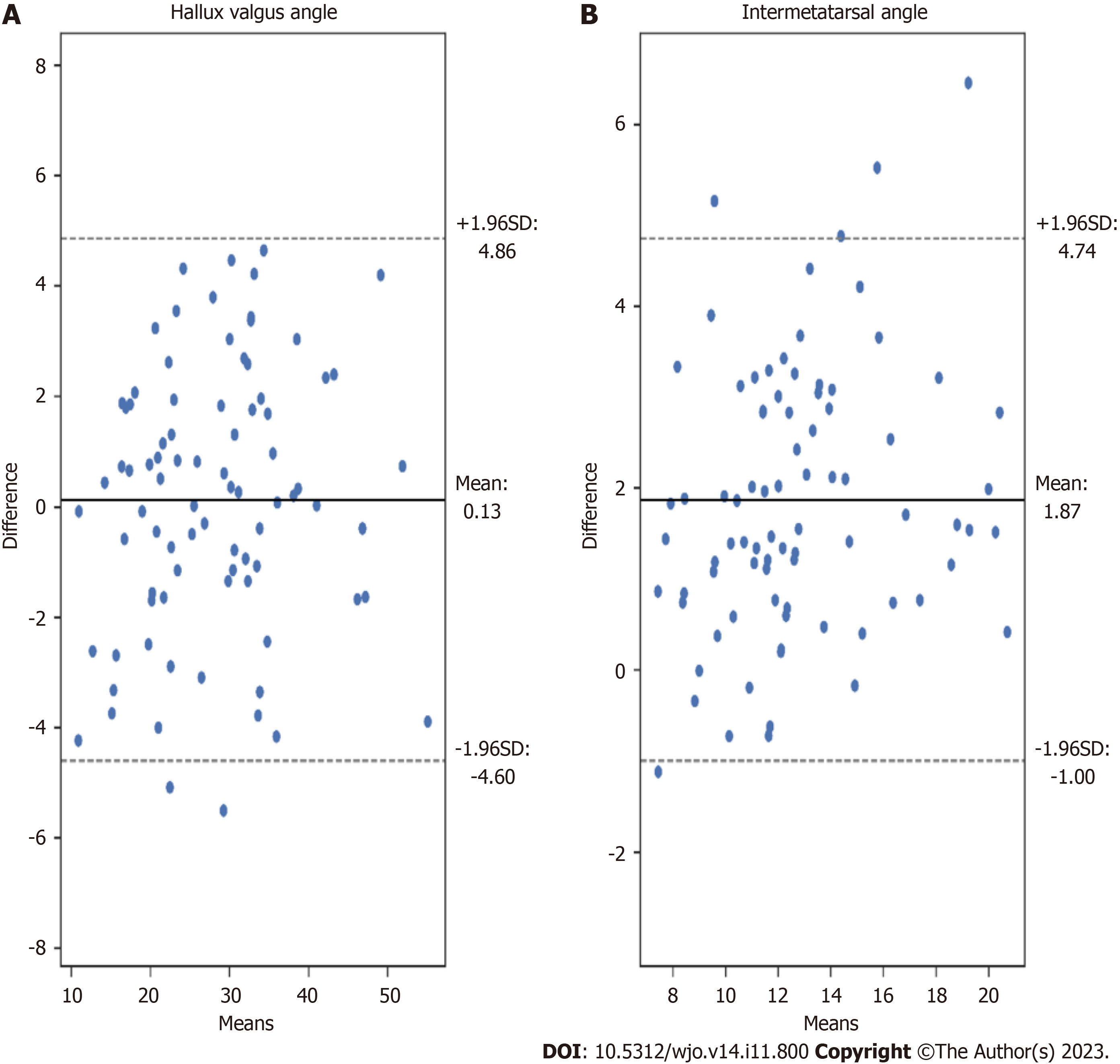
Figure 7 Bland-Altman plots illustrating the differences between measurements achieved by our algorithm (AI) and orthopedic surgeon (OA2).
A: Hallux valgus angle measurements; B: Intermetatarsal angle measurements.
- Citation: Kwolek K, Gądek A, Kwolek K, Kolecki R, Liszka H. Automated decision support for Hallux Valgus treatment options using anteroposterior foot radiographs. World J Orthop 2023; 14(11): 800-812
- URL: https://www.wjgnet.com/2218-5836/full/v14/i11/800.htm
- DOI: https://dx.doi.org/10.5312/wjo.v14.i11.800


