















©The Author(s) 2017.
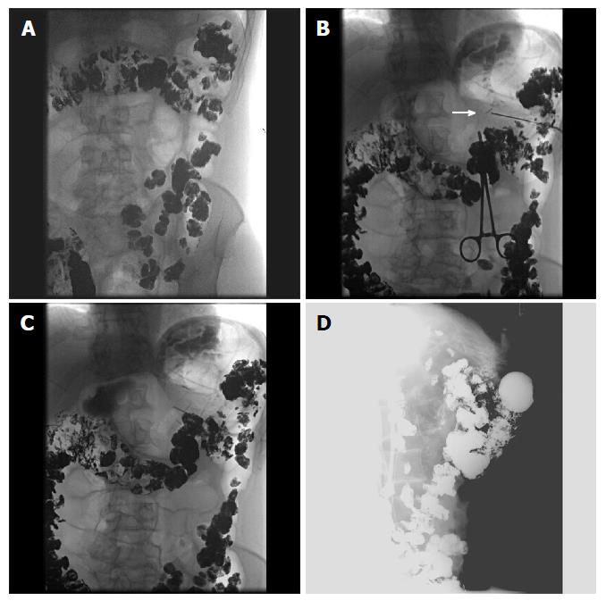
Figure 7 Selected fluoroscopic images demonstrating fluoroscopically guided gastrostomy placement.
A: Contrast seen throughout the transverse colon; B: The first T-tac (white arrow) is deployed following needle insertion into the gastric lumen; C: Two more T-tacs placed; D: Static lateral image of the gastrostomy tube against abdominal wall and not in the colon. The contrast is injected into the tube to demonstrate intraluminal placement.
- Citation: Ray DM, Srinivasan I, Tang SJ, Vilmann AS, Vilmann P, McCowan TC, Patel AM. Complementary roles of interventional radiology and therapeutic endoscopy in gastroenterology. World J Radiol 2017; 9(3): 97-111
- URL: https://www.wjgnet.com/1949-8470/full/v9/i3/97.htm
- DOI: https://dx.doi.org/10.4329/wjr.v9.i3.97