
















©The Author(s) 2026.
World J Transplant. Mar 18, 2026; 16(1): 110683
Published online Mar 18, 2026. doi: 10.5500/wjt.v16.i1.110683
Published online Mar 18, 2026. doi: 10.5500/wjt.v16.i1.110683
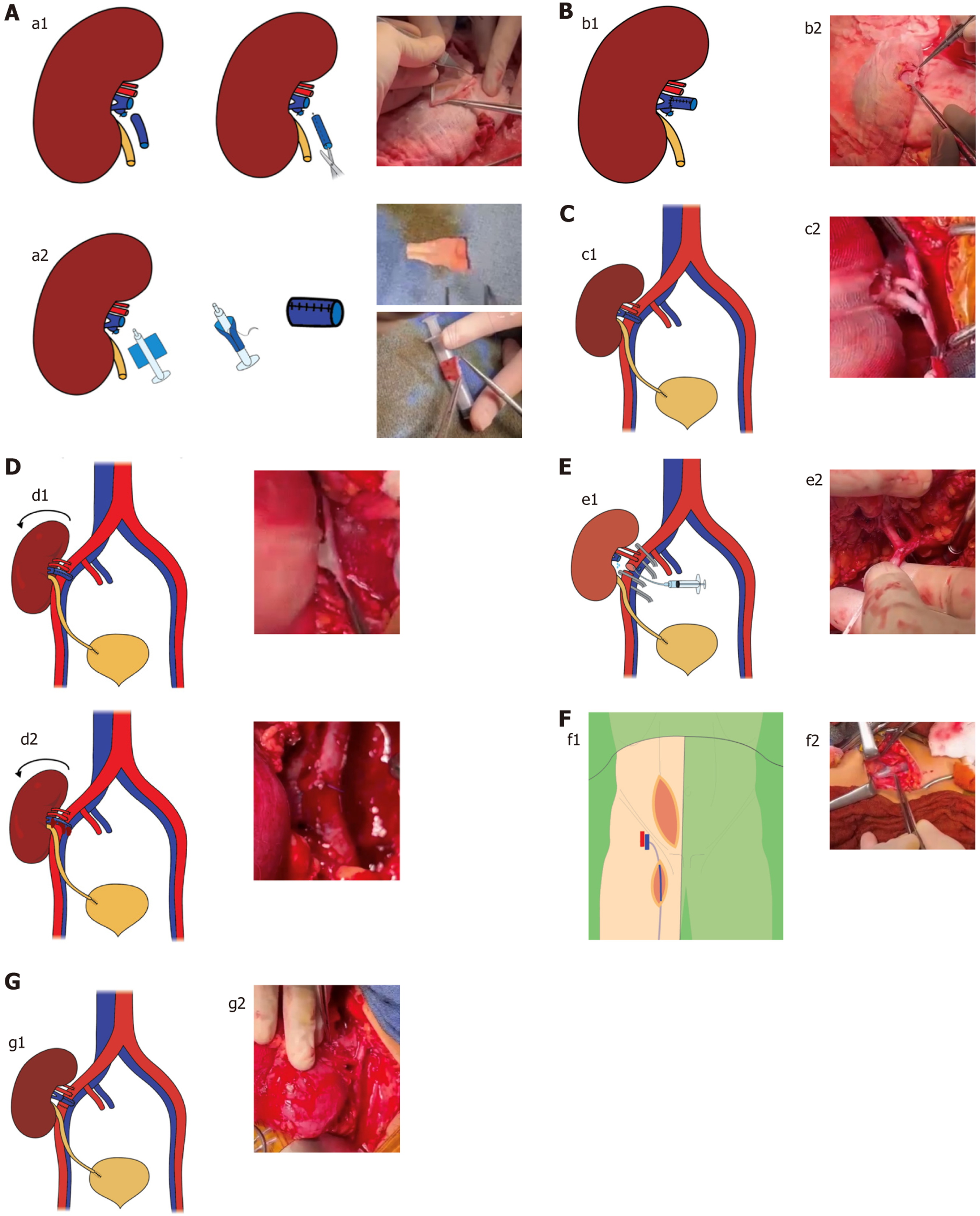
Figure 1 Fabrication of the vascular cuff and related surgical diagrams for case 1.
A: Creation of a cylindrical vascular cuff. a1: Longitudinal opening; a2: Syringe molding of the donor’s gonadal vein for renal vein extension; B: Venous cuff fashioned from the donor’s gonadal vein, modeled into a tubular shape, and anastomosed end-to-end to the donor’s renal vein to achieve venous extension. b1: Schematic illustration; b2: Perioperative image; C: Anatomical configuration of renal allograft in the right iliac fossa. End-to-side anastomosis of the reconstructed renal vein via gonadal venous cuff to the external iliac vein and renal artery to external iliac artery. c1: Schematic illustration; c2: Perioperative image; D: View following declamping and graft repositioning. d1: Significant tension present at the venous anastomosis site; d2: Bleeding observed at the level of the reconstructed venous cuff; E: After identifying bleeding at the venous anastomosis, the iliac vessels were reclamped, and the external iliac artery was transected to facilitate graft flushing and maintain perfusion. e1: Schematic illustration; e2: Perioperative image; F: Harvesting of the recipient’s saphenous vein in the right groin and reconstruction of the venous cuff. f1: Schematic illustration; f2: Perioperative image; G: Anatomical configuration of renal allograft in the right iliac fossa. End-to-side anastomosis of the reconstructed renal vein via saphenous venous cuff to the external iliac vein and renal artery to the external iliac artery. g1: Schematic illustration; g2: Perioperative image.
- Citation: Lekehal B, Ait Youssef N, Lekehal M, Bakkali T, Jdar A, Bounssir A. Vein cuff interposition for short renal vein in living-donor kidney transplantation: Three case reports and review of literature. World J Transplant 2026; 16(1): 110683
- URL: https://www.wjgnet.com/2220-3230/full/v16/i1/110683.htm
- DOI: https://dx.doi.org/10.5500/wjt.v16.i1.110683